So after installing the diode the circuit has been running for about 2 hours with a 1 sec on and off time and so far no damage to any components.
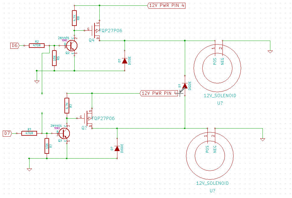
Now I have attached another drawing to show a different route for controlling the two solenoids
I have moved it between the two drains...my thinking is if pin 7 MOSFET is on it will also feed the other solenoid, but if PIN 6 is on it only feeds the one solenoid.
Also I'm using a 1N4000 diode for all diodes in the drawing.
let me know what problems I may run into if I go this route but at least the MOSFET's are staying alive
So after installing the diode the circuit has been running for about 2 hours...
From the first you stated that you had "the diode" in place.
I have been using the attached circuit [showing "the diode"]... I have placed a freewheel diode in the drawing.
But you weren't afterall or something?
Referring to the circuit with "the diode" and actually using it are two or three different things?
Please, don't set me straight - I'm confused enough as it is.
Hi, you should be using software to do what you are trying to accomplish with the extra diode.
This will apply less stress to the hardware.
Tom......
For a quick recap.
What is happening is the MOSFET and transistor are being zapped, but the diodes remain okay.
Can we have a picture of the assembly of transistor and MOSFET and diodes please.
this is why fast diode and not standard slow 1N400x are required. because the high back EMF voltage from the coil kill the transistor before to be damped by the diode.
some transistors can be killed simply by taking them without protection (by electrostatic discharge)
dark1990:
So after installing the diode the circuit has been running for about 2 hours with a 1 sec on and off time and so far no damage to any components.
It certainly should be working in that case, but the question we must now ask is - where was the diode before?
dark1990:
Now I have attached another drawing to show a different route for controlling the two solenoids
I have moved it between the two drains...my thinking is if pin 7 MOSFET is on it will also feed the other solenoid, but if PIN 6 is on it only feeds the one solenoid.
No, that is very bad. That will mean one transistor will be powering both solenoids in parallel at some stage, which will be stressing it excessively and unnecessarily. Better to use the circuit dlloyd illustrates, though his explanation is confused or confusing.
dark1990:
Also I'm using a 1N4000 diode for all diodes in the drawing.
I sure hope not! A 1N4000 is an obsolete stud-mount 7.5V 10W Zener diode. Care to explain what you really mean??
I see someone touched on a opto coupler. Would this really be the way to go? I can also switch out the transistor for a opto just not sure which one would work best.
It was TomGeorge, and it really is the best way to go. Some parts I would suggest using are PS2501-1 and 1N5408.
From the specs, it's a bit overkill, however these parts are readily available and not very costly.
As a suggestion, here is the opto-isolated circuit:
IN4001 to 1N4007 diodes would also work ... there's no extra cost to get higher blocking voltage, i.e. 1N4007.
So I didn't make it clear enough in my first post. I kept smoking MOSFETS (10 to be exact) without the diode. I then read and researched MOSFETS and inductive loads I then came across the flywheel diode.
I then placed it in my drawing. Before I added the diode I posted on here to make sure it was in the right spot as I had only 1 MOSFET left before I needed to order more.
Once you guys said it was correct I tried it with success. I then wanted to know if I needed to add anything else to protect it further.
I also meant 1N4001 sorry about the typo but I will place a larger one in the final design.
I will change the code and remove the diode from the two solenoids source.
I did run the circuit for 6 hours straight and the only issue I had was the solenoid got extremely hot. However the solenoid is not designed for long durations so for my purpose it will work just fine. They may operate 5-10 min in a 8-10 hour period
I may try an opto circuit for the isolation alone since I aslo need to do a N channel MOSFET to control a 36v circuit on the same board.
dlloyd:
IN4001 to 1N4007 diodes would also work ... there's no extra cost to get higher blocking voltage, i.e. 1N4007.
Which is in general, a great convenience for stocking, but since the diode is never exposed to anything beyond the supply voltage itself, there is no actual benefit in this case.
Excellent circuit with the opto-coupler.
We have now acquired a large grey double quotation mark!