hi all,
i recently got a esp12f, which has 2 rx/tx pins, 5v and gnd. I have been puzzeled on how to use it. it also came with a ftdi programmer, with txrx pins too. it seems to have some sort of example sketch too, bcuz when connected to pwer a wifi ap is created, and i cant open serial monitor to check output bcuz idk how to use ftdi programmer. Pls help!
Have you tried searching the web for a diagram to show you how to connect the programmer to the esp?
Perhaps you could post links to the components you have.
I didnt find any links for this product, since its from china and a friend gave it to me, and finding a product on china web is like finding a needle in a haystack. But i did take some photos:


USB/TTL     ESP12E

5V     -->   VCC
VCC    -->  (to USB/TTL 5V)
3.3V
TXD    -->   RXD
RXD    -->   TXD
GND    -->   GND

The USB/TTL 5V need to connect to the USB/TTL VCC AND to the ESP32 VCC
connecting a ESP12F to a USB-TTL module (logic set to 3.3V)
USB-TTL GND to ESP12F GND
USB-TTL 3.3V to ESP12F VCC
USB-TTL TXD to ESP12F RXD0
USB-TTL RXD to ESP12F TXD0
resetting the device serial monitor displays the bootup information at 74880baud
Jan  8 2013,rst cause:2, boot mode:(3,7)

load 0x40100000, len 27728, room 16
tail 0
chksum 0x2a
load 0x3ffe8000, len 2124, room 8
tail 4
chksum 0x07
load 0x3ffe8850, len 9276, room 4
tail 8
chksum 0xba
csum 0xba
rf[112] : 03
rf[113] : 00
rf[114] : 01

SDK`�HN�
at 115200 baud it displays "ready" and responds to AT commands
SDK`�HN�{$l��|�d�|
�l�
#|����r�#�c��'o�dog���c
8�lrd;lx�o�
�
d
#g�|��Ǐ
�c��o'�l��l`�eogl ao;���g
cl�`x�o�
;�����
#g�|�$��#��no�
d`�eog�$'{���g
�lx�n�
{�����l�co�|l��Ǐc��go��l`�ogl n{���g
ce�`as��n
c�`��s�l�$�
�l ��{�l�le�
l`��;�d
ǟ�
ld`{l��{�
ready
AT
OK
AT+GMR
AT version:1.1.0.0(May 11 2016 18:09:56)
SDK version:1.5.4(baaeaebb)
compile time:May 20 2016 15:08:19
OK
photo

uploaded File>Examples>ESP8266WebServer>HelloServer to ESP-12F
when run it connects to WiFi network and runs a HTTP web server - serial monitor displays
.................
Connected to XXXXXXX
IP address: 192.168.1.165
MDNS responder started
HTTP server started
A useless web hook has passed
(this hook is in 0x402010ac area (401x=IRAM 402x=FLASH))
A useless web hook has passed
(this hook is in 0x402010ac area (401x=IRAM 402x=FLASH))
on PC Firefox web client connects and displays
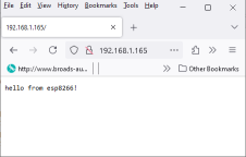
but for some reason when the ttl converter is powered by 3v3 it dosent recieve serial messages. I tried powering it from a outside source but now it dosebnt show up as a port on my raspverry pi, pls help
and btw, what are at commands?
The general concept is explained here:
When you purchase an ESP8266 module, it often comes from the manufacturer with a firmware loaded that allows you to control the module by sending certain "AT commands" via the module's serial interface. You can learn about the AT command interface of the ESP8266's firmware specifically here:
There are different versions and variants of the firmware, and there are some differences in the AT command set between them. So depending on which firmware happens to be loaded on your module you might find that the documentation I linked above doesn't apply perfectly. But you will likely find that the basic commands documented there still work with your module, and regardless it will provide enough information to answer your question.
There are two common ways the ESP8266 is used by the Arduino community:
- As a WiFi adapter module controlled by a standard Arduino board (e.g., Uno, Mega) over a serial connection using AT commands. In this usage, you will be writing Arduino sketches for and uploading to the standard Arduino board, not the ESP8266.
- As a standalone Arduino board. In this usage, you will be writing Arduino sketches for and uploading directly to the ESP8266.
If you decide on the first usage, you can either hunt down the documentation for the specific AT firmware on your module, or else install the firmware you want.
If you decide on the second usage, the sketch you upload to the ESP8266 will replace the AT firmware so you won't need to think about AT commands at all.
Actually i think this is supposed to be used as an external module. How can i check? btw ty for the at commands link!
the ESP-12f can be used
- as an external WiFi module connected (using Serial IO) to a host such as a UNO, Mega, etc controlled via preprogrammed AT commands
- stand alone running your own code (see post 6 for an example of a ESP-12f running a web server)
in the latter case, because the ESP-12f does not have a USB connector to program the device, you have to use an external programmer to load code into the ESP-12f - see Connecting to ESP-12E/ESP-12F Board Via USB
I tend to use a ESP-01 Helper V3 for programming such ESP8266 modules
Why are you powering at 3.3V when the ESP needs 5V.
Why didn't you connect as I explained in post #4 20 days ago?
I am. I power it using 5v, but then i need a external power source to power the usb adapter. I figured that out. What im saying is that i have to power both with 5v, which ik how to do. I need help trying to figure out how to use it with a arduino as a :external module: like u mentioned
This topic was automatically closed 180 days after the last reply. New replies are no longer allowed.