I am using an Arduino Mega for a university project, in which I want data from a temperature sensor to be transferred to Cloud via a ESP-01 ESP8266 module, and whatever I do I get shown the same error:
A fatal esptool.py error occurred: Failed to connect to ESP8266: Timed out waiting for packet header
Note1: I have the following cabling, which I assume is correct:
VCC: 3,3V
GND: Ground
URXD: TX1
UTXD: RX1
CH_PD: 3,3V
GPIO0: Ground
RST: Reset
Note2: this happens even with a blank code.
Any suggestions?
Yes and yes - RX on the module is connected to TX1 (pin 18) and TX on the module is connected to RX1 (pin 19).
I am lost about the second question - no idea on how that can be done
a note I also forgot - I've also selected the correct board (generic ESP8266 board) and the correct port which is COM3 in this case.
First of all you need a voltage divider on the esp-01 rx pin to reduce the 5v logic level to a safe 3.3v
i use Mega TX -> 1K -> ESP-RX -> 1K -> 1K -> GND. You will damage the esp (or you maight have done already) if you omit that.
What you need to do is upload the Serial Passthrough example into the mega and set the baud rate for both Serial ports to the baudrate that is used for upload, which is 115200bps by default
void setup() {
  Serial.begin(115200);
  Serial1.begin(115200);
}

void loop() {
  if (Serial.available()) {      // If anything comes in Serial (USB),
    Serial1.write(Serial.read());   // read it and send it out Serial1 (pins 0 & 1)
  }

  if (Serial1.available()) {     // If anything comes in Serial1 (pins 0 & 1)
    Serial.write(Serial1.read());   // read it and send it out Serial (USB)
  }
}
ESP8266 datapins are all 5V tolerant. The myth that they are not is a misconception from the beginning when not much documentation was available. At a later moment Espressif personnel confirmed that datapins are 5V-tolerant.
To program the ESP-01 the boot pins should have the right level. To boot in programming mode your pin levels are correct (CH_PD high, GPIO0 low).
Note that you need to trigger reset prior to uploading the new firmware. At time of reset GPIO0 should be low to trigger programming mode.
Next you also need to make sure that VCC is very stable. Sometimes a capacitor or better power supply is useful.
To test your connections you can use the Arduino IDE serial monitor after triggering reset to see what the ESP produces. If it looks like garbage you should set the right baud rate for boot messages. This is somewhat unusual 74880 baud.
If you see readable text the connection is okay.
NOTE: Make sure to close the serial monitor prior to pressing reset again for programming.
(BTW. If you would be using the ESP-01 as a serial module using the default ESP serial firmware (for sending AT-commands) you are not programming the ESP-01. In that case you are programming the Mega and you should select the Mega board instead of ESP8266 generic.)
First picture is with the ESP board selected (upload speed was set to 115200 on everything, no connection), the other one is with the Mega board selected (serial monitor said the serial port was busy even though I only have the arduino connected).
The blue light on the ESP blinks for a tiny bit when the output transition happens.
I tried resetting the ESP prior to uploading and disconnecting GPIO0 from LOW, but no change.
I don't believe it's ESP hardware related; I tried 2 modules and the error still shows up. Is there any firmware I need to download and am probably missing?
Or is there any error on the Arduino board itself that doesn't allow it to transfer data to the ESP module?
Any suggestion on how many μFs should the capacitor have?
They aren't but if you want to burn them that is fine. The statement that they are has been retracted.
A nodeMCU usually does have diode to protect GPIO 3, but an ESP-01 has no protection at all.
You need to upload that to the Mega. select that board, and then after that you can upload to the esp.
Basically GPIO0 needs to be LOW at boot, after that reset can be pulled up, there is also a pullup on the board already, so you can also leave it open.
close all applications and re-open the IDE. select the Mega and try uploading the SerialPassthrough Then switch to generic esp8266 and try uploading something simple like blink. There is a blue LED on GPIO 1 (TX) (active LOW) so you can select that as the ledpin, in fact you can do this in the IDE in the tools menu, or just manually select GPIO 1.
Okay, I got that part working, now Serial1 appears in the debug as well.
Now the app tells me that COM3 cannot be opened because it's busy, which is weird because it shows up even after restarting both the arduino IDE and my PC and ensuring no other app uses COM3 as a port.
Can you tell me where I can see the retraction? I don't at all doubt your word, but I would like to add this information to the existing notes I have on the subject.
I only want it for the network capabilities, so I can transfer my data (temperatures from a LM35 sensor, which also affect a LCD and the servomotor angle) to a cloud server
I can quite understand why this was posted in the Mega category of the forum but as it seems to be about both a Mega and an ESP8266 I've moved it to programming.
As for the ESP8266 being 5V tolerant, while I do not know the official position on this I do know I and others have had problems with slightly high input voltages on ESP8266 inputs, see:
I've seen other similar reports on the forum occasionally.
I'm very interested to see that retraction. I don't want to rail this thread off-topic, but still want to know how to treat my ESP's. I mostly found confirmation of 5V tolerance, e.g. in this topic on letscontrolit, but just did some more reading to find the final answer.
Version 4.3 of the datasheet (2015) states on page 17:
All digital IO pins are protected from over-voltage with a snap-back circuit connected between the pad and ground. The snap back voltage is typically about 6V, and the holding voltage is 5.8V. This provides protection from over-voltages and ESD. The output devices are also protected from reversed voltages with diodes.
The later release v7.0 (2023) is much shorter and doesn't have that text.
This reddit discussion is also interesting and gives mixed findings, but ends with a link to this blog article (2021) gives a summary of various official statements, confirming 5v tolerance.
This Hackaday post (2022) reports about experiments on an ESP-01 to determine factual 5V tolerance. In the comments you can find this reaction by Espressif employee @Sprite_tm. Since I consider Jeroen to be one of the most gifted people in the field I'll take his word as the final answer (for now
As an Espressif employee, this is what I know about this. Note that of these, only the first point is official advice.
– Datasheet says 3.6V. Don’t go make a million devices that put 5V on an IO, and then cry to us when they stop working or blow up or wash your laundry too hot or whatever. 5V is out of spec, we cannot guarantee that it works at 5V as we have no one (e.g. TSMC) to give us these guarantees and the need for 5V compatibility is too low to do full production continuous burn-in tests on that with all the bells and whistles. (And there may be other reasons, I don’t know.)
– That being said, it’s well known that with a series resistor, the chip certainly won’t blow up immediately and the only reasons we know why it might break are somewhat vague (as in: quantum tunneling might do something). I don’t think we have heard of anyone breaking their ESP because (and only because) of 5V applied via a series resistor; it seems to work out for a fair amount of people. If you are OK with taking all the risk that may or may not be there, I wouldn’t stop you from using this hack.
@Deva_Rishi - do you have a link to that retraction? I also like to have my information updated.
No i can't. Every once in a while somewhere here shows up with the statement that esp8266 pins are 5v tolerant, because some CEO said so years ago, and it got posted on FB, but as far as i remember their legal department decided it was better not to state that.
They tend to break when exposed to 5v+ when the GPIO is in output and HIGH 3.3v. It's the reverse voltage that is causing issues. But since some of the pins go HIGH momentarily at boot (and that includes rx, tx, and a few more) They just tend to break.
This added note by Sprite_tm somewhat clarifies Espressif's position on this:
As far as I understand it, the thing is, designing it to be 5V tolerant is not something you can do yourself easily. You’re bound by the process that you use for your chip manufacturing (e.g. the 40nm TSMC process) and that gives you certain guarantees (‘if you use this-and-this mosfet, the gate is sure to withstand 3.3V’). From what I heard, TSMC doesn’t have guarantees for the process we use for 5V, so we’d be on our own in designing it and would have to validate it for each production batch to make sure nothing changed that ‘broke’ the design.
That is a valid method and that is what i am suggesting. The way through just the USB to TTL converter is also an option. of course.
Here we are again helping people with their homework.
I think it is best to adopt a 'They are not 5v tolerant policy' since the people who claim otherwise are not taking responsibility for the consequences.
If it was available to upload to the Mega, it should still be available, but be sure not to open multiple instances of the IDE. Be sure to close the Serial monitor.
Not much point in posting screenshots, they are very hard to read.
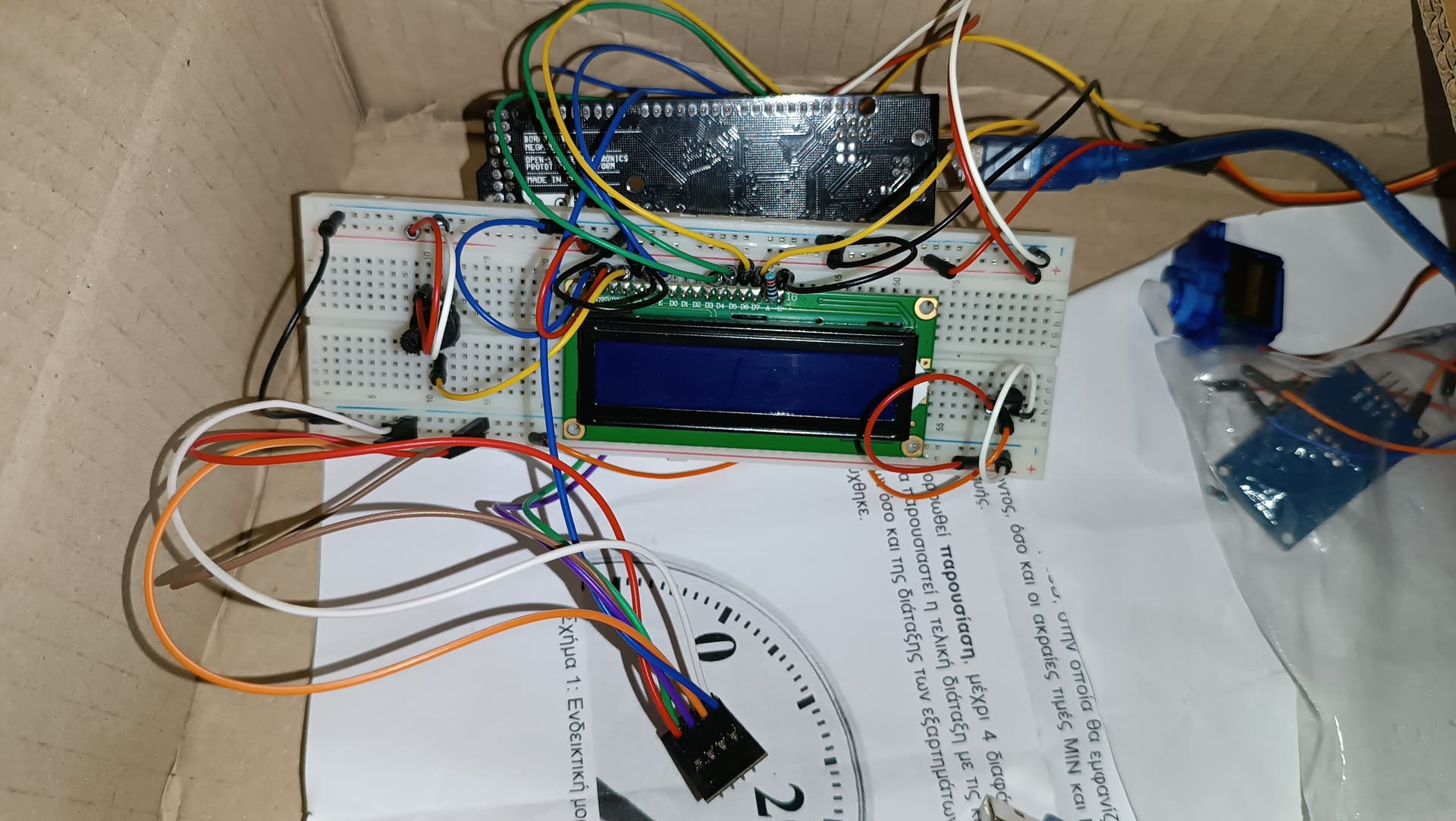
Do i see an ESP-01 serial adapter module on the right there, still in plastic ? Use that ! it has level shifting and even a dedicated 3.3v regulator (though the Mega 3.3v should suffice) and should protect your ESP-01