I am making a Ventilator for corona. Those who wish to support please welcome. My Arduino code will be available for everyone.
I can guide online for the control part. I need support also for some parts. My email is vidyaratna@gmail.com.
Is there anyone who has Arduino air pressure sensor. If so can I work online to check some thing ( To detect when someone inhale) Currently i have no access to go out door to buy a sensor.
The sensor in question would presumably be the BMP280.
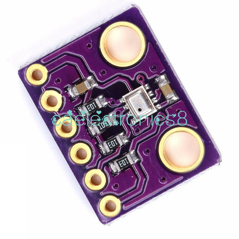
I would be reasonably certain that this will assess respiratory pressures entirely adequately for the task. It is an absolute sensor, so you would use a pair, one for ambient and one for circuit pressure.
I think you should outline your project in extensive detail. Your post has been moved from "project guidance" but many here will collaborate openly on the forum.
The design plan is attached. I need the support for PS1 sensor. (BPM280 or other) This sensor should detect when the pressure drops when try to inhale and trigger.( ie. AC230v relay switch for v1 solenoid valve open and v2 close)

FiO2 value (Fraction of inspired Oxygen) and PS2 sensor trigger value ( according to IPAP) will be input using keypad. V3 and V4 open times will calculated using FiO2 and IPAP.
We need to do the changes IPAP when the unit is working. ( the keypad data input should not interrupt V1 and V2 valve open and close time pattern. The transition should be smooth.)
Ongoing incomplete code is attached herewith. All who can support are welcome.
sensor testing .txt (9.34 KB)
A few of those details need "fleshing out". Use of water valve for PEEP is interesting.
I gather that green object adjacent to V1 is a bag - not sure how that is supposed to work. For oxygen efficiency you would prefer re-breathing but that is presumably too much of an ask. I get the impression that your column in the middle is the delivery pressure bellows using a weight for calibration, not sure how you will make it work smoothly.
Use of a sensor at the mask leads to two concerns, sterilisation and cabling distance. Do you expect to have filters to use? I have seen a DS18B20 mounted on the end of a metre of heater wire along an insufflation hose, but in any case, the sensor is better mounted in the equipment, on the right hand side of V2. In "first world" equipment this would all be disposable but I wonder how much you expect to re-use?
Let me assure you that properly designed software (not looked at yours yet) will allow operation as smooth as your valves permit.
Be sure to initial and date that drawing. It qualifies as a Design Input Document for when you submit your 510(k)
![]()
Thank you Paul_B for your reply with comments. That bag near V1 is to create some air to breath if V1 close before the patient finish his inhale. AND to act as a pressure chamber after closing V1.
What kind of valve should we use here if water valve is not suitable. (water valve is ok or not please give your idea.)
The column in the middle is two PVC pipes (Top pipe outside). Top pipe will move up due to pressure created by v4 air first and V3 O2 second and will stop when it hit the Tidal volume adjustment bar at the top. It will not come down more than marked volume.
yes we can put the heat sensor on the right hand side of V2.
At the end of inspiratory hose there should be a pressure sensor to detect the inhale. Wire to the sensor will be going outside the inspiratory hose (attached to it at the end)
Dear cedarlakeinstruments i can not understand the line "when you submit your 510(k) " Is it a fine or penalty.
I have no money earning intention here.
Is there some one who can support on air volume measurement. It is better to measure exact volume of air that pass out through V1. ( it should equal to tidal volume)
sanjeevsrilanka:
Is there some one who can support on air volume measurement. It is better to measure exact volume of air that pass out through V1. ( it should equal to tidal volume)
hall effect ( or reed type) flow sensor should do it
all you do is measure air flow rate, and over time you get to calculate the volume
Thank you KASSIMSAMJI for the input. Is it possible to know a model number which work with arduino mega. or If you can add a image that would be great.
see this link
they are named 'water flow sensor' but i confirm they work with air ( low pressurized systems, like in respiration ) too
they need at least 1 liter/min of air flow rate ( may be less for small sized ones ? ) , not sure if that can be met in your system
and yes they work with Mega ( it literally needs an interrupt pin )
Thanks KASSIMSAMJI. They say that "the average adult at rest inhales and exhales something like 7 or 8 liters"
So it is more than the 1 liter/min. I can use it.
I like to propose with a simple solution under following restrictions in the design.
If they are running out of proper ventilators.
Proposed solution:
eg: If you need 50 ventilators for one large hall.
we can do the controlling of all 50 ventilators by staying in a outside control room.
we need one O2 and Air mixed line ( one FiO2 value) for all Patients. Normal manual type control valve at each bed.
A Large PVC line to connect Expiratory line.
The patients Inspiratory line is connected to " the O2 and Air mixed line" through a (AC power) large solenoid valve in the correct direction.
Expiratory line also connected via another large AC power solenoid.
For the solenoid valves AC neutral line (N) is common for all.
Two line wires (L) from each solenoid should laid to the control room.
These two lines will be connected to the " Arduino Two relay module" one line from AC (N) will come to the relay module and then joint to the two relays.
So each Arduino mega board will have
- 2-relay module ( 2 in one board)
- keypad
- I2C type 16*2 display
- removable USB port type phone charger (5V DC input power to Arduino board given through USB)
all the 50 Arduino boards are connected to large white board size board. keypad and relay should fix. Each Arduino mega board should numbered clearly to identify the patients bed number.
(if the AC power is not stable for all AC power should go via lardge UPS .)
Control person can key in * and ( 4 digit code relevant) ( to chane the default pattern)
For each patient different inhale and exhale time duration s can set.
( each Inspiratory line and expiratory solenoid open and close duration should program for each Code number)
for 4 digits we can set different settings as guided by the doctor.
we can load the program to 50 Arduino boards with in less than one hour complete setup can be finished in one day.
when the doctor wants to do change the inhale exhale time duration s he can do so by making a call to the control room.
Additionally, we can connect two colour AC indicator lamps (connect parallel to each solenoid )to easily visualize the solenoid open and close times.
pressure adjustment should done using the manual valve.
If anyone interested to use the above method pls send me an email I will send you my the Arduino Code.
thanks
Sanjeev
In the US, a medical device must receive FDA (Food and Drug Administration) approval before it may be put on the market. The product you are developing clearly falls within the definition of a Medical Device. It makes no difference whether it is sold or free, it must first be approved under penalty of law. Filing a 510(k) is part of the process of requesting approval.
Most countries have similar regulations.
sanjeevsrilanka:
Dear cedarlakeinstruments i can not understand the line "when you submit your 510(k) " Is it a fine or penalty.I have no money earning intention here.
cedarlakeinstruments:
Most countries have similar regulations.
Did you notice from which country he hails?
Hint: the handle! ![]()
YES *******