HELP! Simple MIDI Buttons and LED's sketch

Hi.

First off, I'm rubbish at maths and programming - C++ is a complete mystery to me.

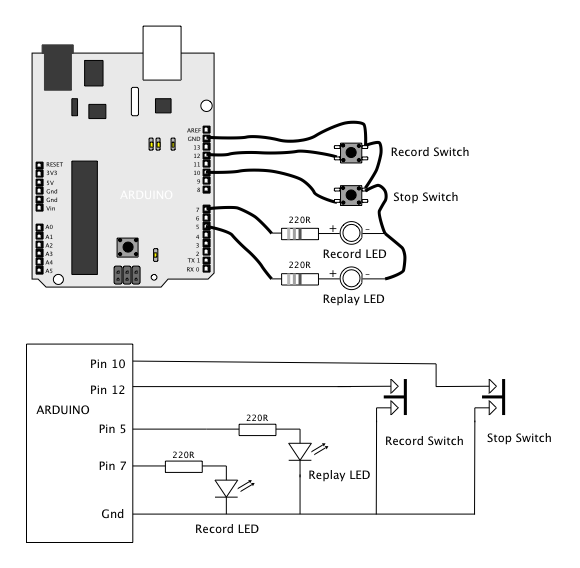
I have built a FootPedal with 4x Momentary Switches and 4x LED's.
This is for controlling ONE channel of a Looper for 3 Musicians (A B C)
The Circuit is here (but it is a MICRO not a UNO board - JPG :

The Sketch, however, is beyond me.
I have studied numerous examples, but they are all very different (libraries, serial, etc.), so very hard to know what is best to do, and most of them won't even compile successfully.

I have started a Sketch with the basics (Pin definitions for Switches and LED's), but I am lost in the MIDI stuff, and getting the PINS>MIDI and MIDI>PINS is a mystery.

Could some kind soul take my basic Sketch and complete it please?

Here is the Sketch code with notes for the PIN numbers and MIDI Notes :


// START SKETCH
/*

Concept by William Hitchings, 09-2023

SKETCH to run a MIDI FOOTPEDAL comprising of :

  4x Momentary Switches (Pins 5-6-7-8) to trigger specified MIDI notes.
  4x LEDs (Pins 9-10-11-12) to Flash when specified MIDI notes received.

The Foot Pedal is to operate a 3-Person ( A B C ) Looping Machine built in MAX-MSP.
This Sketch is to operate one of the 3 Controllers, each with their own MIDI Switch numbers. So there will be 2 other controllers with relevant MIDI notes for Players B and C.
Hence why some parts are copied and greyed out, for the other controllers.
The LED's are for Tempo Counters, so the MIDI is the same for all controllers.

I understand the 'concept' of arrays, but since I only have 4 switches and LED's it seemed easier not to use them.

This runs on an ARDUINO MICRO board.

MIDI SWITCH NOTE NUMBERS
========================
37 = REC A
39 = DEL A

42 = REC B
44 = DEL B
46 = RESET

49 = REC C
51 = DEL C

54 = OVERDUB A
56 = OVERDUB B
58 = OVERDUB C

MIDI NOTES TO FLASHERS
======================
40 = LED-1 
41 = LED-2
47 = LED-3
48 = LED-4

PIN NUMBERS
===========
SW1 = 5
SW2 = 6
SW3 = 7
SW4 = 8

LED1 = 9
LED2 = 10
LED3 = 11
LED4 = 12

*/

#include <USB-MIDI.h> // ?? Correct Library ?

USBMIDI_CREATE_DEFAULT_INSTANCE();

unsigned long t0 = millis();
unsigned long tClock = millis();

using namespace MIDI_NAMESPACE;

midiEventPacket_t read(void);
void sendMIDI(midiEventPacket_t event);
void flush(void);

// const uint8_t button1 = 2;

/*
#define SW1Pin 5  // SWITCH PINS
#define SW2Pin 6
#define SW3Pin 7
#define SW4Pin 8
        
#define LED1Pin 9   // LED PINS
#define LED2Pin 10
#define LED3Pin 11
#define LED4Pin 12   
*/


int SW1Pin = 5;  // SWITCH PINS
int SW2Pin = 6;
int SW3Pin = 7;
int SW4Pin = 8;
        
int LED1Pin = 9;   // LED PINS
int LED2Pin = 10;
int LED3Pin = 11;
int LED4Pin = 12;


int val = 0;

void digitalWrite(uint8_t pin, uint8_t val);
void digitalRead(uint8_t pin, uint8_t val);

void setup(){
  {
  // Set MIDI baud rate:
  Serial.begin(31250);

MIDI.begin(1);              // Launch MIDI and listen to channel 1
}

{//     LED FLASHERS 
pinMode(LED1Pin, OUTPUT);
pinMode(LED2Pin, OUTPUT);
pinMode(LED3Pin, OUTPUT);
pinMode(LED4Pin, OUTPUT);

}

{ //    MIDI SWITCHES 
pinMode(SW1Pin, INPUT);
pinMode(SW2Pin, INPUT);
pinMode(SW3Pin, INPUT);
pinMode(SW4Pin, INPUT);
}

}

void loop() {
   MIDI.read();
  {
 // read the SWITCH input pin
{
val = digitalRead(SW1Pin);  
val = digitalRead(SW2Pin);
val = digitalRead(SW3Pin);
val = digitalRead(SW4Pin); 
}
// write to LED output pin

digitalWrite(LED1Pin, HIGH);
digitalWrite(LED2Pin, HIGH);
digitalWrite(LED3Pin, HIGH);
digitalWrite(LED4Pin, HIGH);

                       // Received a MIDI message

    {
      { digitalWrite(LED1Pin, HIGH); // LED 1 ON
      delay(300);
      digitalWrite(LED1Pin, LOW);
      }

      { digitalWrite(LED2Pin, HIGH);  // LED 2 ON
      delay(300);
      digitalWrite(LED2Pin, LOW);
      }
    
      {digitalWrite(LED3Pin, HIGH);  // LED 3 ON
      delay(300);
      digitalWrite(LED3Pin, LOW);}
    
    {  digitalWrite(LED4Pin, HIGH);  //  LED 4 ON
      delay(300);
      digitalWrite(LED4Pin, LOW);}
   
    }
    }
    
    {    
 MIDI.sendNoteOn(37, 127, 1);    // Send Note 37 (REC-A), velo 127 on channel 1)
        delay(100);		            // Wait for 100ms
        MIDI.sendNoteOff(42, 0, 1);     // Stop the note

 MIDI.sendNoteOn(39, 127, 1);    // Send Note 39 (DEL-A), velo 127 on channel 1)
        delay(100);		            // Wait for a second
        MIDI.sendNoteOff(42, 0, 1);     // Stop the note

 MIDI.sendNoteOn(54, 127, 1);    // Send Note 54 (DUB-A), velo 127 on channel 1)
        delay(100);		            // Wait for 100ms
        MIDI.sendNoteOff(42, 0, 1);     // Stop the note

 MIDI.sendNoteOn(46, 127, 1);    // Send Note 46 (RESET), velo 127 on channel 1)
        delay(100);		            // Wait for 100ms
        MIDI.sendNoteOff(42, 0, 1);     // Stop the note

    }

void flush(void);
}

// END SKETCH

If someone could help, I'd be eternally grateful!
I'm not sure if the Libraries I'm using are appropriate or not, since the code seems very dependent on the correct Libraries to work.

Thanks again in advance!

WillH

The millions of options that you (theoretically have) can practically be divided into two options:

Option 1: investing money:
if you explicitly do not want to learn programming pay for a ready to use device which could be bought off the shelf or could be developed by somebody that writes all the code for you.

Option 2: investing personal time:
learning to program yourself. By asking not only this one question you asked above but working through basic tutorials and asking dozens of questions

maybe there is an option 3:
Asking in a fablab near to where you live if there is a person that finds it intriguing to write the code for such a device.

best regards Stefan

Arduino Micro or Mega? Those pin numbers.

Well you don't wire up push buttons like that. It is very easy to get a button rotated by 90 degrees so if you wire them across the diagonal it will always make a circuit through the button when pressed. Also note that you don't need that resistor at all if you enable the internal pull up resistor on each input pin.

The code like you suspect is not good and will not work. Just for starters this bit

This puts all the input switches into the same variable so in effect only the last of these four lines will control your code.

Hi xfpd

Those are MIDI Note Numbers, not Pin Numbers!

Sorry, I thought the // commenting explained each section.

This puts all the input switches into the same variable so in effect only the last of these four lines will control your code.

Even using 4 different names?
I'm even more confused now!

RE: Switches - I have seen that some circuit diagrams use a 5v 'third wire', and some don't, just PIN+GND wires. It is easy enough to add in the 5v wire if it needs it. I have tested the contacts in the switches I'll be using, they are definitely momentary.

Thanks for the help.

Yes because you are taking what you found by reading the SW1Pin and putting it into a variable called 'val'

Then you are taking what you found by reading the SW2Pin and putting it into a variable called 'val'. So now the variable val only contains what you found by reading SW2Pin. This variable has replaced what it previously contained.

Repeat this for the SW3Pin, and the SW4Pin and all that is left is a variable 'val' that contains what was on the SW4Pin and nothing else.

AHHH! yes I see. I thought each was a separate 'definition' of the name.

You don't want to do that at all.

Yes there are quite a lot of bad circuits out there on the net.

There is no need for the two braces { } at the start and end of these definitions. And they should be

pinMode(SW1Pin, INPUT_PULLUP);
pinMode(SW2Pin, INPUT_PULLUP);
pinMode(SW3Pin, INPUT_PULLUP);
pinMode(SW4Pin, INPUT_PULLUP);

So they activate an internal pullup resistor. Then you just wire the input pins to ground directly. Then when you read them a push will return a LOW and an un-pushed button will read as a HIGH.
This is the proper way of reading push buttons, any other way is rubbish, and shows the designer of the circuit hasn't got a clue about what they are doing.

In fact the variable 'val' is not used in the code in any meaningful way so it is a waste of time defining them. The code is indeed a pile of rubbish, full of unnecessary braces { } and devoid of any if statements that would make it work. Are those doubts commented in the code yours or those of the original author?

This is how you should wire up push buttons

Hi. Thanks for the help!
Yes, the code is rubbish - as I said, I know nothing...

But you must know what you want that code to do?
In the original comments it was said:-

The Foot Pedal is to operate a 3-Person ( A B C ) Looping Machine built in MAX-MSP.

So unless you have access to this MAX-MSP code you are not doing what the original author wanted to do.

So what do you want it to do?

hi bro.iam having some issues with my project could u look into it.

No.
Please start your own thread.
What you are trying to do is to hijack this thread and this is against the forum rules.

You might want to look at this How to get the best out of this forum before you proceed any further.

The MAX-MSP project was written by me.
The Sketch was started by me, using info from the Web - which is usually not 100% accurate, or not the same project as I want to achieve, so having to guess the appropriate methods for this project.
The Foot Pedal is really simple, just 4 buttons sending triggers into MAX, and 4 LED's flashing tempo from MAX.
I'm surprised it is not far easier to achieve, as it is so simple.
But Arduino has so MANY different boards, libraries, etc. it's no surprise.
I think I am also confused between 'Serial' and 'Midi' options - I didn't realise they were two different comm methods.
So I have started a separate Sketch for the Serial option. This seems to use simpler code, but not as 'PnP' as the Midi version.

The serial option is only applicable if the thing you are trying to connect to has a 5 pin DIN MIDI interface. So what is the sort of interface that your MAX-MSP sketch is expecting?

The board is plugged into PC via USB. No 5-pin involved.
Strange, I was just looking at this video :

and he is using 'Serial' in the IDE but no 5-pin plug, just USB straight into the PC. Obviously I have changed the 'Analog' read to 'Digital' as it is just a button not a pot.
But regardless of how accurately I copy stuff, it doesn't work, and I have no idea why.

The MAX-MSP project has mappings for Midi inputs at the moment, but they are easily exchanged for Serial controls instead.

Because you are not doing it right. It is OK for him to say there is no need to worry about the details, but honestly there is.

Not had time to watch it all, but the only way to use an Arduino Uno R3 is to have a helper app inside the computer using something like Hairless. That converts USB serial data into MIDI data.

If you have a Micro or Leonardo then there is no need to use serial. But you have to get your code right, which you have not by a million miles.

I have to go on a trip now, but I will be back this evening.

1 Like

Try this, it compiles for a micro but otherwise untested, but it is a lot closer than you had. I had to use arrays because the code got too tedious without.

/*
 * MIDIUSB_test.ino
 *
 * Created: 4/6/2015 10:47:08 AM
 * Author: gurbrinder grewal
 * Modified by Arduino LLC (2015)
 * and Grumpy Mike 29/9/2023
 */ 

#include "MIDIUSB.h"

//.................................
//MIDI SWITCH NOTE NUMBERS
//========================
char REC_A = 37;
char DEL_A = 39;

char REC_B = 42;
char DEL_B = 44;
char RESET = 46;
char REC_C = 49;
char DEL_C = 51;
char OVERDUB_A = 54;
char OVERDUB_B = 56;
char OVERDUB_C = 58;

//MIDI NOTES TO SEND
//======================
char MIDInotes1[] = {REC_A, REC_B, REC_C, OVERDUB_A};
char MIDInotes2[] = {DEL_A, DEL_B, DEL_B, OVERDUB_B};
char MIDInotes3[] = {0, 0, 0, OVERDUB_C};

//PIN NUMBERS
//===========
char SW[] = {5, 6, 7, 8}; // switches to monitor
char LED[] = {9, 10, 11, 12}; // LEDs to flash

char channel = 0;
char noteVelocity = 127; // maximum velocity

// Define routines to send data
// First parameter is the event type (0x09 = note on, 0x08 = note off).
// Second parameter is note-on/note-off, combined with the channel.
// Channel can be anything between 0-15. Typically reported to the user as 1-16.
// Third parameter is the note number (48 = middle C).
// Fourth parameter is the velocity (64 = normal, 127 = fastest).

void noteOn(byte channel, byte pitch, byte velocity) {
  midiEventPacket_t noteOn = {0x09, 0x90 | channel, pitch, velocity};
  MidiUSB.sendMIDI(noteOn);
  MidiUSB.flush();
}

void noteOff(byte channel, byte pitch, byte velocity) {
  midiEventPacket_t noteOff = {0x08, 0x80 | channel, pitch, velocity};
  MidiUSB.sendMIDI(noteOff);
  MidiUSB.flush();
}

// First parameter is the event type (0x0B = control change).
// Second parameter is the event type, combined with the channel.
// Third parameter is the control number number (0-119).
// Fourth parameter is the control value (0-127).

void controlChange(byte channel, byte control, byte value) {
  midiEventPacket_t event = {0x0B, 0xB0 | channel, control, value};
  MidiUSB.sendMIDI(event);
  MidiUSB.flush();
}

void setup() {
  Serial.begin(115200);
  for(int i = 0; i<4; i++){
  pinMode(SW[i], INPUT_PULLUP);
  }
  // all LEDs off
  for(int i = 0; i<4; i++){
  pinMode(LED[i], OUTPUT);
  digitalWrite(LED[i], LOW);
  }
  noteOn(channel, RESET, noteVelocity); // send reset note
  delay(100);
  noteOff(channel, RESET, 0);
}

void loop() {
  // Check if you need to send any notes then send them and flash the LEDs
  for(int i = 0; i<4; i++){
    if(digitalRead(SW[i]) == LOW){
      noteOn(channel, MIDInotes1[i], noteVelocity);
      noteOn(channel, MIDInotes2[i], noteVelocity);
      if(i == 3) noteOn(channel, MIDInotes3[i], noteVelocity);
      digitalWrite(LED[i], HIGH);
      delay(300);
      noteOff(channel, MIDInotes1[i], 0);
      noteOff(channel, MIDInotes2[i], 0);
      if(i == 3)noteOff(channel, MIDInotes3[i], 0);
      digitalWrite(LED[i], HIGH); 
    }
  }
    delay(30); // account for contact bounce
}
1 Like