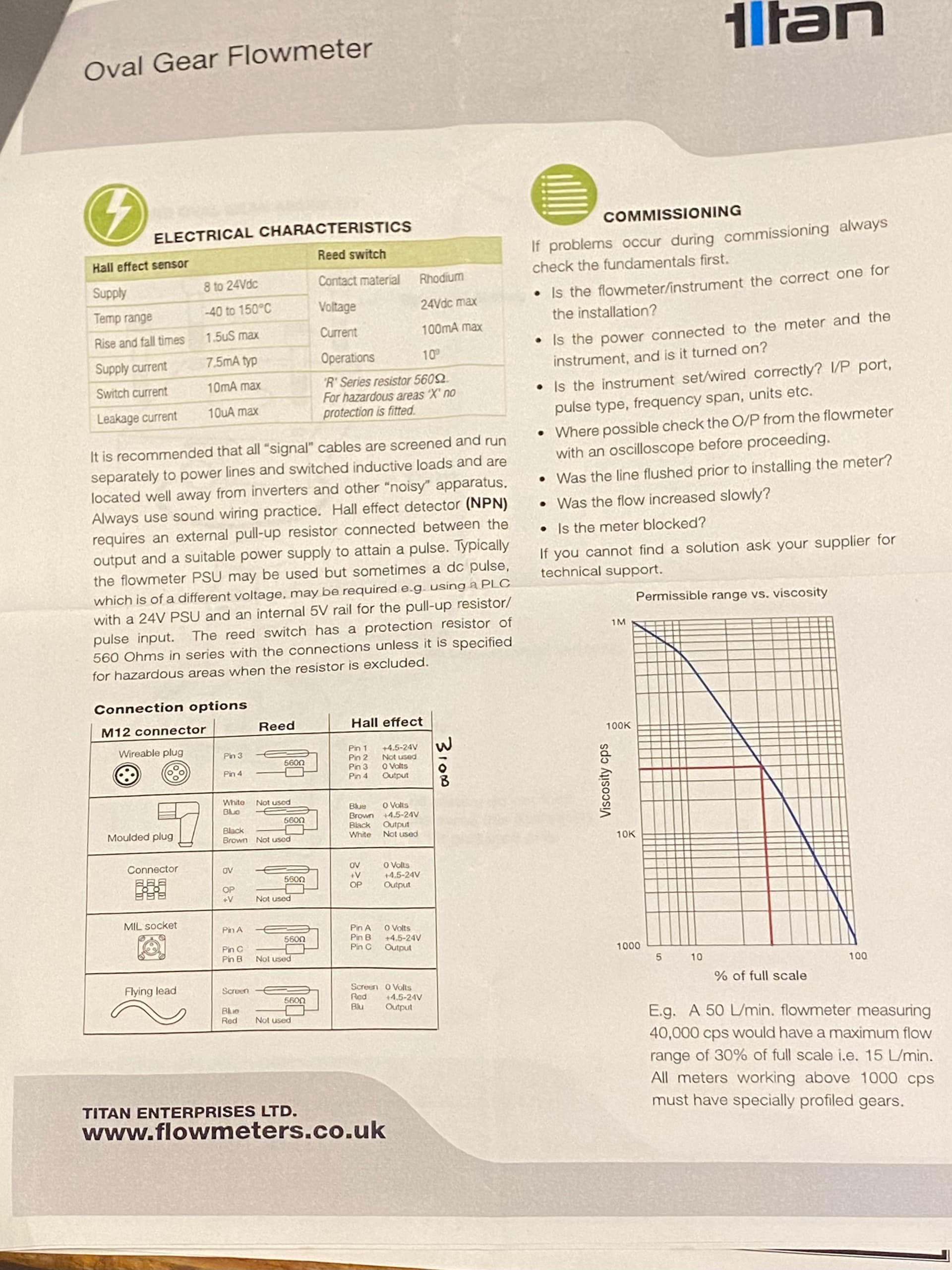
From the paperwork (below) it is a hall effect sensor NPN with needs a pull up resistor between output and positive.I have wired it in my breadboard to be Pin 1 5V, Pin 3 Ground and Pin 4 to Pin 2 (interrupt) on the Nano with a 10k pull up resistor going to 5V
Sorry, should have linked it but I was more focused on wiring so i ignored the code.
ignore the // talking about serial, i changed it to print to the lcd but didnt remove the // comments
#include <LiquidCrystal_I2C.h>

#include <Wire.h>

LiquidCrystal_I2C lcd(0x27, 20, 4);

int flowPin = 3;    //This is the input pin on the Arduino
double flowRate;    //This is the value we intend to calculate.
volatile int count; //This integer needs to be set as volatile to ensure it updates correctly during the interrupt process.

void setup() {

  lcd.begin(20,4);

  lcd.init();
  lcd.backlight();
  lcd.setCursor(0,0);
  // put your setup code here, to run once:
  pinMode(flowPin, INPUT);           //Sets the pin as an input
  attachInterrupt(1, Flow, RISING);  //Configures interrupt 0 (pin 2 on the Arduino Uno) to run the function "Flow"
  Serial.begin(9600);  //Start Serial
}
void loop() {
  // put your main code here, to run repeatedly:
  lcd.setCursor(0,0);
  lcd.print("Flow: ");
  lcd.print(flowRate);        //Print the variable flowRate to Serial
  lcd.print(" ml/min");
  count = 0;      // Reset the counter so we start counting from 0 again
  interrupts();   //Enables interrupts on the Arduino
  delay (1000);   //Wait 1 second
  noInterrupts(); //Disable the interrupts on the Arduino

  //Start the math
  flowRate = (count * 1.185);        //Take counted pulses in the last second and multiply by 2.25mL
  flowRate = flowRate * 60;         //Convert seconds to minutes, giving you mL / Minute
  flowRate = flowRate / 1000;       //Convert mL to Liters, giving you Liters / Minute
  lcd.clear();
}

void Flow()
{
   count++; //Every time this function is called, increment "count" by 1
}
Wiring seems OK (if you then put cables from sensor correctly). Check voltage on signal pin (with voltmeter) try short this pin to ground with wire and check if counter counts. Try this with connected sensor and disconnected.
About code: don't disable all interrupts, they are needed for core Arduino functions. And they are default enabled. If you want stop "receiving" external interrupt disable only this one or add global flag in Flow() to return immediately:
Try to connect your interrupt input to Vccc and GND to to see if the Arduino part is OK.
Measure with a DMM what kind of voltage levels your sensor generates in series with the pull up resistor.
No, you must use noInterrupts()/interrupts() around critical sections on the AVR microcontrollers - these queue pending interrupts rather than dropping them on the floor.
However you shouldn't disable interrupts for any longer than necessary, here it just needs a short critical section:
Hi,
How many terminals does YOUR sensor have, the "circuit" you posted shows 4 terminals with 3 connections.
BUT
The datasheet you posted only shows 2 connections need to be made for reed switches.
The link in RS gives this. https://docs.rs-online.com/3649/0900766b815eefbb.pdf
What is the actual pinout, a link to where you got it would help.
What part number does your sensor have printed on it?
Have you written some simple NON-Interrupt code to test that you are getting a signal?
Forget about displaying anything on LCD, just make the on board LED blink.
The device has 4 pins. The datasheet is attached in the original post says the following, hense why I wired it above to follow the four pins of the datasheet.
0G23499
Yeah realise I went a little too hard too early on that. I will try that.
We need the full part number from your sensor to determine if the output is a reed switch or hall sensor.
As for the sensor approach, the max flow is ~ 4 liters / minute resulting in a max pulse rate of approx 13 ms. So unless you are doing a lot of other stuff you really don't need an interrupt although one could be used.
You can also use a timer counter in a number of configurations.
Rotation is detected through the chamber wall by a Hall effect detector or
a reed switch giving approximately 1100 pulses per litre
passed. The output is an NPN pulse or a voltage free contact
closure either of which is readily interfaced with most electronic
display or recording devices.
Is there anything wrong with using interrupts? Im a self-taught so forgive the naivety. it just seemed cleaner as it will just record the rising which in my head was simple.
Once I have the flow meter working my plan is to record the total count (ie total water dispensed) as well as have the flow rate per calculated in a millis() 1 second loop thats already part of the main code.
The final destination for this flow meter has a bit of code running. It's not overcomplicated code but it will basically control a solenoid for 10 hour to flow water with float switch for overflow detection. the flow meter to measure to total volume of water passes as well as display rate per minute. I also have an LCD output and a Wi-Fi module (ESP-01) that plan for the future but i haven't worked that in yet so the code
This is why I thought an interrupt was cleaner so it can just ++ on every pulse.
Thanks for the help Tom you bloody legend. (From Melbourne)
I run my own small business and I've been super under the pump lately so haven't had time yet to have another play since posting this. The main reason for my post was to make sure the wiring was right as I'm actually making a PCB right now that covers all of the sensors, transistors, diodes and resistors etc that support the solenoid, float switches outputs and inputs and i wanted to include the flow meter in the PCB for future prototypes so needed help confirming my layout. I will test it out on Friday maybe Monday but appreciate the help
Hi @hamshi4 ,
Sorry if I'm mistaken, but the "scheme" shows the sensor connection connected to pin D2 and the interrupt selected in the code is 1 (D3).
Has this been fixed yet?
@TomGeorge I finally got some time to work on this and having a hard time getting anything working.
I've been trying to get any reading out of this device and just cant seem to get it working.
Firstly, I have tested out the code above with plastics flow meter below and it works fine, so I'm getting very confused because they are both hall effect flow meters.
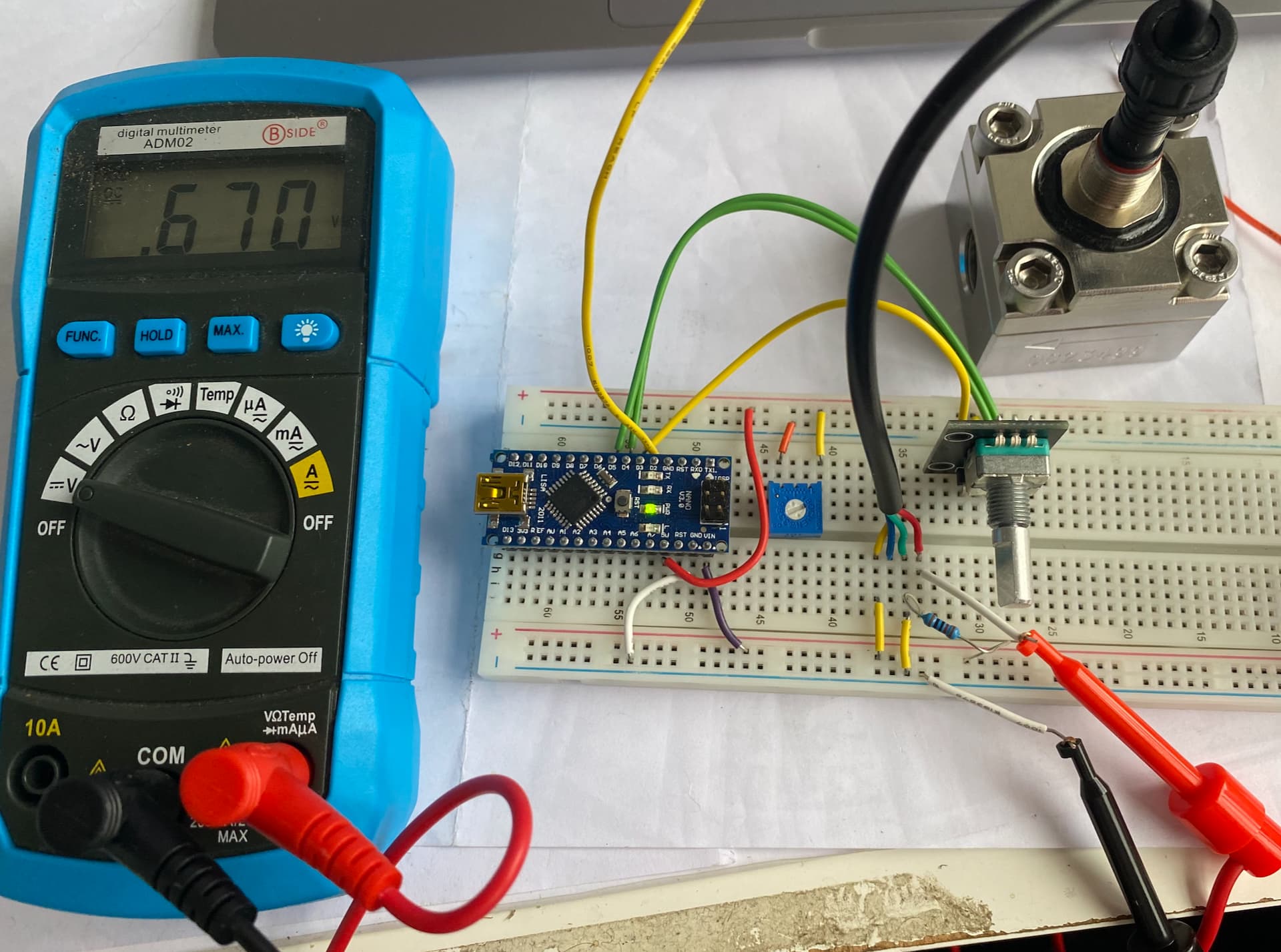
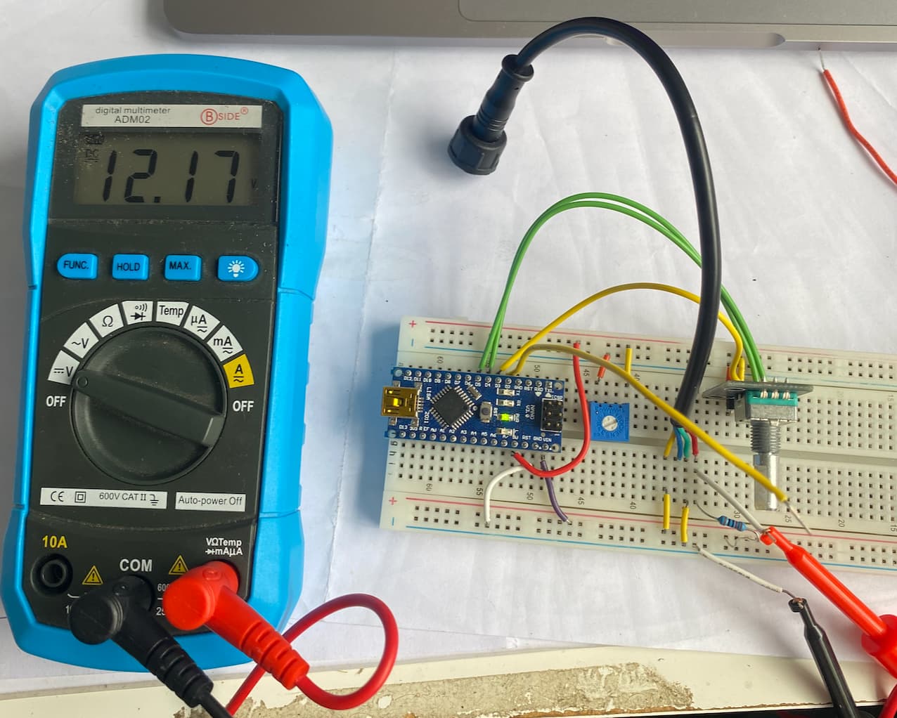
Again I'm new to this so I might be doing the testing with a DMM wrong, so please correct me if I am.
With these DMM tests I blew into the flow meter and can hear it rotating but I can't see anything change on the DMM.
Pin 1 thru to 4 are in order from left to right. Ignore the trimpot and rotary encoder, the trimpot is for the LCD that is disconnected.
I also have two of these devices purchased a year apart, so although possible, the likelihood of it being a faulty device is low.
I also was testing at 12V. Dont worry, this wouldn't be directly connected to the nano, this was just for the DMM test as I was concerned that 5V might be the issue.