I have an Arduino (well, a Teensy) in a project which is battery operated and includes a small LCD and an ADS1115. Use is on demand, and is only required for a few seconds at a time, and a handful of times in a short period. And then most likely dormant for a few days.
It's running on a 400mA LiPo battery.
I know I could use a physical switch, and that would make life easy, but I prefer to have a timeout power off. And for some reason I always seem to find the hardest way to want to do things.
I've implemented sleep routines that turn off as much as possible, and wake on a button connected to digital input. This drops total power consumption to about 8mA in this state. Which is fine for use every few minutes. But I want to drop it even further during extended power off periods.
I have a few modules at my disposal, and I'm not sure how to make them all work together.
I'll start with an Adafruit PowerBoost 500C. That allows me to charge the battery from a USB port, while also powering the device via a built in 5v (actually 5.2v) regulator. The PowerBoost's regulated output is ON by default, and will draw 4mA even with nothing connected. But if the enable (EN) pin is shorted to GND, the output circuit is disabled and drops battery current consumption to about 10uA.
So my question is, how can i wire a circuit so that:
With no power to the microcontroller, the PowerBoost EN pin is shorted to ground
Pushing a physical button disconnects the short, thereby turning on the microcontroller (added bonus, this only happens on a 1-2 sec buton hold, although this could be done on the microcontroller startup)
Microcontroller can activate the short-to-ground via a digital output to turn itself off after a timeout.
Same power button that is used to turn the circuit on is also a digital input to signal the microcontroller to shutdown.
I've tried looking at a switching circuit using either an NPN or PNP transister, but I don't know how to short EN to GND with a floating base, and open it with either a high or a low digital output from the microcontroller.
Hope anyone can take the time to read and help me out! (Or point to another way I can solve this problem - my Google-fu has not been strong with this one!)
Forgive me if I'm missing something, but these look to draw quite a lot of power.
The HFD27 datasheets shows that for the 003-H model, which will can be activated through the voltage range of a LiPo, coil resistance is 60ohm. So at 3.7v, thats 62mA of current draw, which is half as much as the entire rest of my circuit, including the Teensy and LCD display.
Could you remove the power enable resistor from the board? So that you can take the enable pin low with a resistor to ground and high with an arduino output? Maybe a mosfet to do additional level shifting?
I hoped that the board would have a jumper to do this, but on the picture from google I do not see any jumpers...
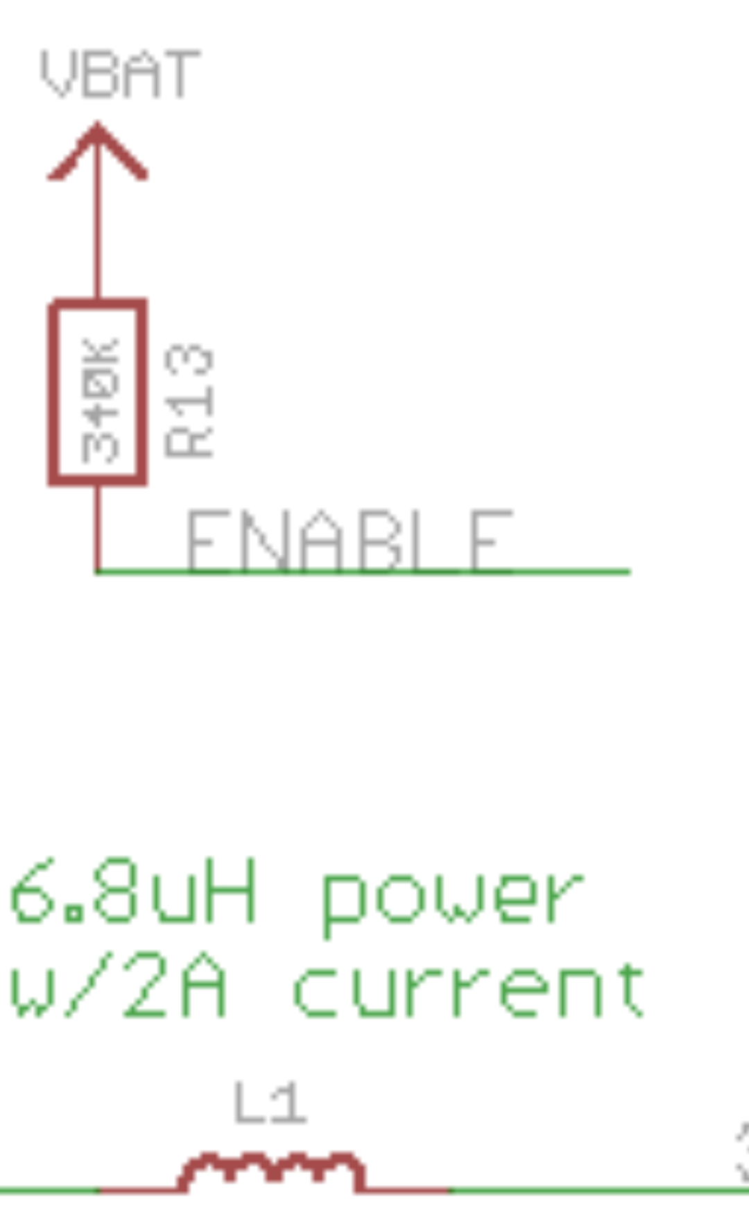
Experiment with different resistor values to find the highest value that will reliably pull the EN pin low and turn the circuit off. Higher is better because less battery power will be drained when the circuit is off. Let's say that's 33K.
Put a push-to-break (normally closed) switch in series with that pull-down resistor. When pressed, the EN pin will be pulled up and the circuit should switch on.
Also connect a Teensy pin to the EN pin via a second resistor. Experiment with that resistor value to find the highest value that will (in combination with the 340K pull-up) overcome the pull-down resistor and keep the circuit switched on. Let's say that's 3K3.
When the circuit is off, the battery will be drained through the 340K+33K, which should be only around 10uA, plus the 10uA consumed by the booster.
The Teensy can keep the power on by setting that output HIGH. Around 100uA will flow from the pin.
The big advantage with using a relay is that you do not need to know anything about the circuit you are connecting to. This is because it provides perfect isolation.
The problem with using electronic connections like a FET is that you need to know exactly what you are connecting to and design your interface to suit. Often this might involve higher voltages like mains which bring its own problems of protection and isolation.
I can't use the 005-S version, as the pick-up voltage is 3.75. A LiPo battery has a nominal output of 3.7V, which will be lower as the battery discharges, so it may not be able to activate the relay.
I've just found a similar thread on the Adafruit forums (https://forums.adafruit.com/viewtopic.php?t=143103), using a MOSFET. I might give that a try, but I'm not sure where to start selecting a suitable MOSFET?
If you want to go the mosfets way, instead of the EN pin, why not cutting the battery power directly? You could use a latch circuit like this:
SW1 will turn it on, the GPIO needs to be switched high to keep it on, and set it low to switch off.
I actually don't mind this idea - The pull-up resistor looks easy enough to desolder, and then assuming that leaving EN floating will not enable the regulator circuit, I just use a push-button to tie and extern 340k resister to VBAT. Sounds about this simplest solution.