Hi:
I am using an SH1106 display and the breakout board has the following schematic:
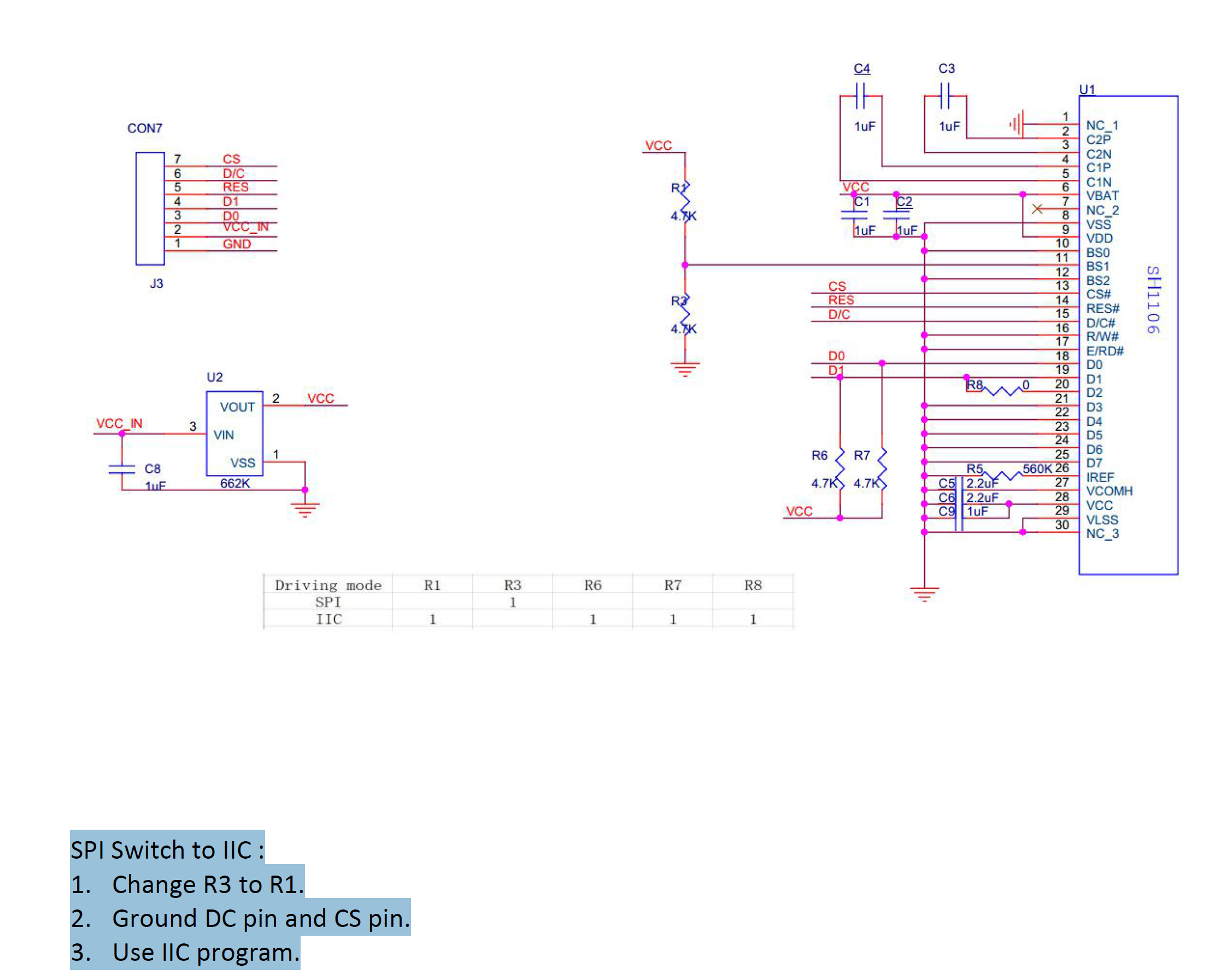
The breakout board has a jumper for I2C or SPI. I am planning on integrating this display on my own pcb and am trying to understand if I need all all of the circuitry that is on the breakout board. The final design will be SPI and have a +3.3V supply.
- The table in the figure shows R6, R7, and R8 are for I2C. R6 and R7 look like pullups for D0 and D1 which I believe are the data lines for I2C. For SPI D0 is SCLK and D1 is MOSI. Do I still need the pullups for SPI? I currently have them in my design and it works, but If I can remove them, that would be better.
- What is the 662K Voltage regulator for? The supply voltage for this design is the 3.3V from an esp32. Is this voltage regulator necessary or a nice to have?
Any input is appreciated!
Fish
