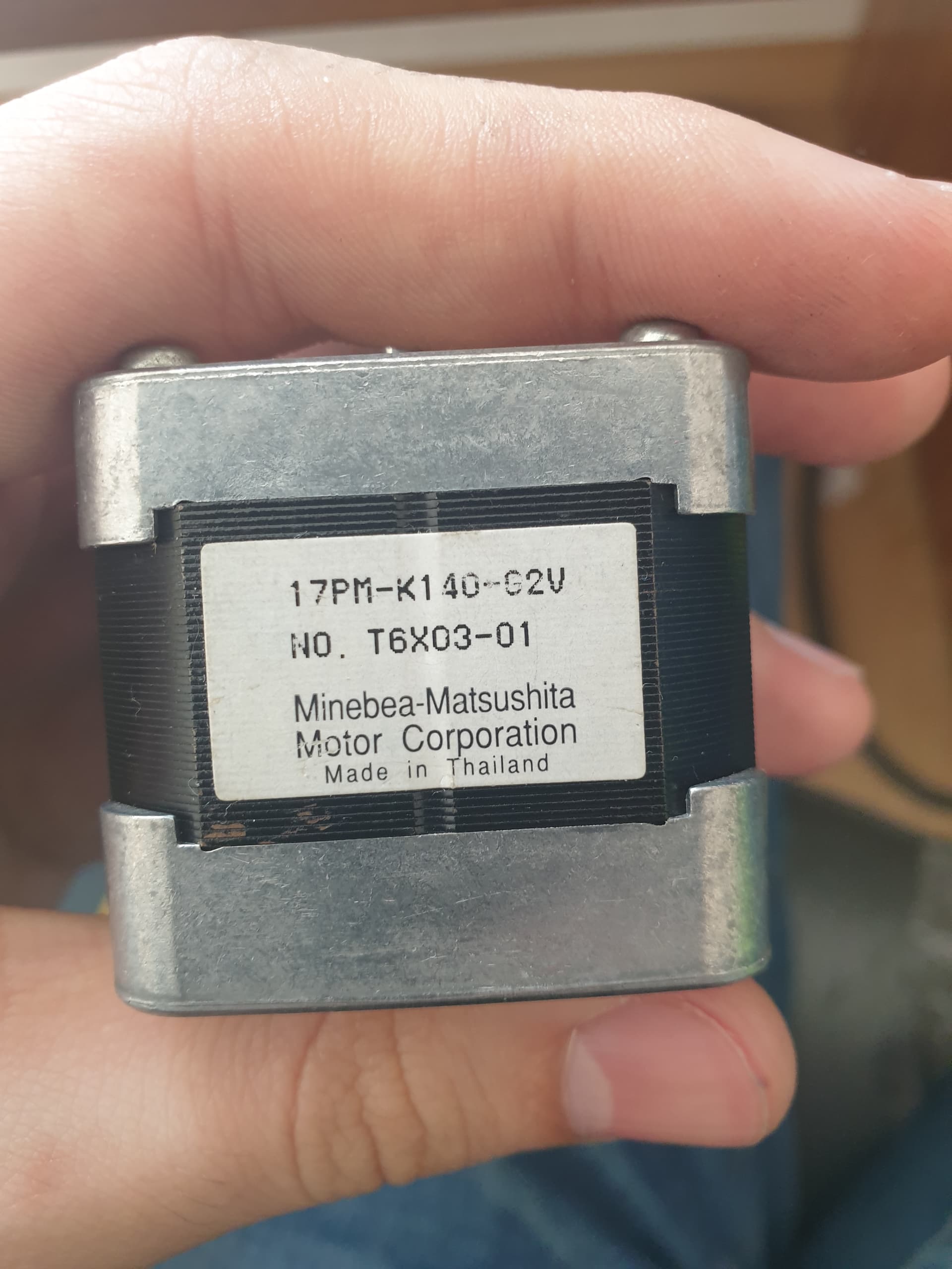
Hi, its me again. So I have this stepper "nema 17" from old printer and it is 6 wire unipolar motor.
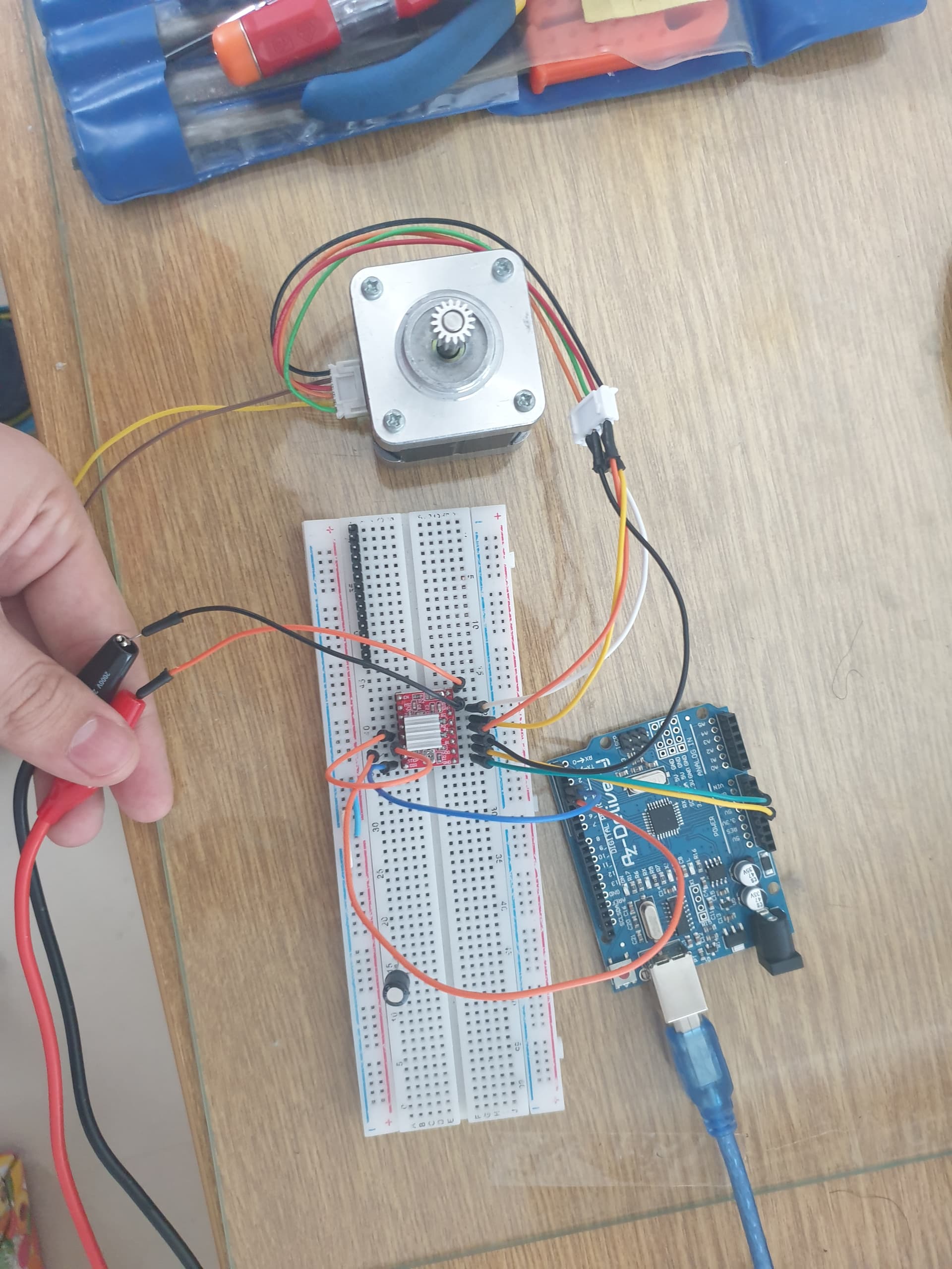
So I connected it to "bipolar" driver a4988 and I left 2 wires, one from one coil and one from another not connected. And I thought that it should work because it is like bipolar stepper if I dont connect two wires but motor wasnt moving, just weird noise was comming from it and motor was stopped (like it was "holding").
So I am looking for some answers why that didnt work.
Use your multimeter to measure the winding resistances, and report those in your next post.
Printer motors are usually high impedance, and won't work with the A4988 unless the motor power supply and current limit settings are carefully and correctly selected.
I measured them and between (look at the photo above), between red and red/white resistance was 3,7R and between other green and green/white was 4 as I can remember.. Measures betwen so (green white etc.) were about half of the resistance between Green and green/white.
That should work with an A4988. You will need a motor power supply of at least 12V (preferably 24V) and set the current limit to 0.5 Amperes/winding as a start.
If you don't know how to set the current limit, read about it in the A4988 data sheet and watch Pololu's video.
The instructions in that video are valid only for their A4988 stepper drivers, so if you have a clone, it will probably have a different current sense resistor, which you must take into account.
And I tried diffrent speed settings... And i also tried it with uln2003 connected as unipolar motor and motor was just jumping back and forth for maybe a step or less. And I also tried it with all 16 possible combinations to connect wires..
Hello. I tried a lot of things, I tried 2 diffrent steppers and they do the same thing.. they are just vibrating and beeping.. I tried diffrent codes too..
It sounds like you might be randomly trying things without understanding the implications that may affect or even destroy the driver.
Take a known good driver.
Ensure it has its heatsink on and secure and is NOT touching any of the pins.
Don't connect the motor at this point !
Turn down the current limiter on the driver but not all the way !
Power up the driver and set the current limiter to just under its requirement as per any specs with your multimeter. If you don't have a multimeter STOP as it is required for almost all drivers.
DO NOT set it higher than needed !!!
Turn everything off and connect the stepper.
Double check ALL your connections.
Apply power but do not try to run the motor so ensure you do not have a sketch on your board that will try to run a motor (see BARE MINIMUM example)
Carefully feel the heatsink. It may get warm but not too hot to touch.
Monitor the temperature on the heatsink for a few minutes to ensure it does not get crazy hot.
If all is well then you can load up a known sketch to the board to make the motor move.
If all is well the motor will perform the specified movements.
If the motor is erratic turn OFF the power and double check your sketch and the stepper motor cable itself. If the cable was from China there is always the possibility that the connections may be wrong and require you to change its connections. I do that with a needle to release the locking tabs and slide out the connector to move to another location but as you are using breadboard you can simply swap them on there too.
I would presume you already checked the motor coils to identify the correct ones so the above step would help you to spot and discrepancies there.
I did everithing in that order before, I googled everithing because I am not stupid and I dont want to destroy everithing..
It gets warm but not hot (I have experience from school).
I tried a lot of diffrent sketches, connections on motor are right (same coil), I tired with connector and with this "cables male-female" so cables arent the problem, I tried 2 diffrent steppers and both are doing same thing ( high beeping noise and vibrating and not turning).
Could you please send me "Bare minimum" sketch please?
I realy dont know what could be the problem.. I tried this many times and it still doesent work.. I measured resistance of steppers coils and are about 3 ohms so I think stepers are working (they arent new).
If that is the main capacitor on the breadboard then it is not connected to anything !
Where do the yellow and brown wires go as they seem to go into thin air ?
Normally that cable is only a 4 wire,
You don't appear to have a common ground either ?
What are you using for the driver supply volts/amps ?
Do you know if your board is a good clone or one of the nasty "wavgat" ones ?
The bare minimum sketch is included with the examples in the IDE.
Also not happy with how close the heatsink is to the pins ! It should be in the middle of the board approx. equal space away from the pins and stuck down using proper heatsink tape or if needed superglue as some cheap heatsink tape often supplied with Chinese drivers becomes pliable with heat and can move. I use superglue here but only a very tiny drop to keep the heat transfer as optimal as I can.
Use my driver in a CNC shield as it provides a much better interface to the Arduino and allows better customisation
NEMA xx only refers to the motor frame size and NOT to the connections required so be aware of that.
I don't know your final application so that, and your current code may also be useful at this point. along with any updated schematic (even if hand drawn)
Sorry for that. I was trying possible combinations and I didnt connect it when I took the photo.
Actualy yes, they are not connected. Stepper uses 6 pin conector so I disconnected 2 wires because I didnt need them (one motor has 2 not connected pins, other is "unipolar stepper" so it has 6 pins..
At first I had common ground but as I saw online, many didnt connect common ground... so my bad.
I use laboratory psu set to 12v and current limitation to 1.5A
Board isnt the best but i measured all conections and everything has good contact.