Help with ModBus RTU Master-Slave: SimpleModbus [SOLVED]

Hello everyone,

as many people on here i've been trying out code throughout the pages and can't get my little RS485 slave to communicate...

i'm using a mega2560 with Serial for debug print, and have connected a MAX481CPA to Serial1 using the same schematic as post #667. the device i'm trying to get data from is a refrigerator thermostat -expert nano 3CF- and although its manual is very explanatory (you can take a look at it here) i can't seem to get it working...

this is my code:

#include <SimpleModbusMaster.h>

#define baud 9600
#define timeout 1000
#define polling 200
#define retry_count 10
#define TxEnablePin 2
#define TOTAL_NO_OF_REGISTERS 10

enum
{
  PACKET1,
  PACKET2,
  TOTAL_NO_OF_PACKETS
};

Packet packets[TOTAL_NO_OF_PACKETS];

unsigned int regs[TOTAL_NO_OF_REGISTERS];

void setup()
{
  Serial.begin(9600);
  Serial1.begin(9600);
  
  modbus_construct(&packets[PACKET1], 2, READ_HOLDING_REGISTERS, 256, 2, 0);
  modbus_configure(&Serial1, baud, SERIAL_8N2, timeout, polling, retry_count, TxEnablePin, packets, TOTAL_NO_OF_PACKETS, regs);
}

void loop()
{
  modbus_update();
  Serial.println(regs[0]);
  Serial.println(regs[1]);
}

as you can see in the specs file, register address 256 that i'm trying to read is the ambient temp from the refrigerator sensor .

all i get in the serial output for regs[0] and regs[1] is zeros...
0
0
0
0
0
.
.
.

any ideas on this one? could the MAX481 possibly be the culprit here? i couldn't find the 485 in any local stores... :\

Thank you for your time everyone!

Hello vagos21, a few things about your code.
You define two packets, but only use one, so remover the second packet, PACKET2 form the enumeration list.
In the setup, you initialise serial port 1 to 9600 baud, when you do not need to as it is done in the modbus configure, so remover it also.

You need to confirm that the nano slave ID number, which is 1 by default I believe, you have 2.
Next, confirm the nano data format, you have 8 bits, no parity and 2 stop bits. You might find SERIAL_8N1 will be more common as the default.

Since this is the Modbus master, something else you can try is to place a delay(500); in the main loop and adjusting the polling delay to a higher value, as it may be too fast for the nano until you know how fast it can respond.

What version of SimpleModbusMaster are you using ?


Paul - VK7KPA

Hi rockwallaby !

You ask about -1 in this code!

Where the array is uint16_t, but you are putting a value of -1 into the array element 15, why ?

My answer is wrong about that...16 bits data and -1 should be 65535, Not as I wrote....negative value :frowning:

In code 1, you have:
Code: [Select]

uint16_t au16data[16] = {
  102, 1415, 560, 1250, 2, 7182, 3012, 8, 0, 0, 0, 0, 0, 0, 1, -1 };

/IQAPPS

Thank you for your time rockwallaby and all the willingness to help! but unfortunately none of this worked, i changed the polling time, added delay, even changed TxEnablePin, tried various slave IDs and speeds, changed number of packets to 1, removed serial1.begin, tried different pullup resistors... but nothing yet, no response... i still get zeroes, which is the same as unplugging the rx/tx cables from the arduino. i don't know if there's no transmission from the chip or if i don't get any response, any way i can test it out with a LED on the A/B terminals of the MAX481?

Edit: i'm using 2V2 of the library

Hi Paul!

Yes I know that about bits...
This project for me is more like to learn more of C/C++ and "microelectronic", I work with commercial stuff and there is like you buy devices and you get have nice manuals, you need "only" to follow them , then is finish, yes it is lite PLC coding but not so much...most finished FB. :slight_smile:

OK, now to this project,
I get slave partial to work, still need to fix with RS485 but that is later question!
I get all registers on HMI, and start to understand modbus much more.

rockwallaby:
So, for example, if you wish to transfer a 32 bit integer, then you first need to bisect it into two 16 bit unsigned integers and then send that via two Modbus holding registers. Then at the receiving end, you can then re-combine and re-interpret the two 16 bit unsigned integers to form a 32 bit integer again.

Yes here is coming, I need help with
How to put in C syntax 2x16 bit...one long/doubel data, I know how to re-interpret it on HMI.
I use TinyGPS++ lib Link lib to extract data I need to send it via modbus. See code I have for now.
You can look on row eg 46 witch is Longitude and TinyGPS++ exctract it as 17.244000 double.
Of course in this code it sends as single 16 bit register and show only 17.

#include <SimpleModbusSlave.h>
#include <TinyGPS++.h> // The TinyGPS++ object

TinyGPSPlus gps;

enum
{
  // just add or remove registers and your good to go...
  // The first register starts at address 0
  SAT,
  LONG,
  LAT,
  ALT,
  HDOP,
  KMph,
  HOLDING_REGS_SIZE // leave this one
  // total number of registers for function 3 and 16 share the same register array
  // i.e. the same address space
};

unsigned int holdingRegs[HOLDING_REGS_SIZE]; // function 3 and 16 register array
////////////////////////////////////////////////////////////

void setup()
{

  Serial2.begin(9600);
  modbus_configure(&Serial3, 19200, SERIAL_8N1, 1, 8, HOLDING_REGS_SIZE, holdingRegs);

}

void loop()
{
  // modbus_update() is the only method used in loop(). It returns the total error

  if (Serial2.available() > 0)    //changed from while to if
    gps.encode(Serial2.read());

  if (gps.location.isUpdated()) //
  {


    modbus_update();

    holdingRegs[SAT]  = (gps.satellites.value()); // Number of satellites in use (u32)eg. 10
    holdingRegs[LONG] = (gps.location.lng());     // Longitude in degrees (double) eg. 17.244000
    holdingRegs[LAT]  = (gps.location.lat());     // Latitude in degrees (double)  eg. 58.213450
    holdingRegs[ALT]  = (gps.altitude.meters());  // Altitude in meters (double) eg. 120
    holdingRegs[HDOP] = (gps.hdop.value());       // Horizontal Dim. of Precision (100ths-i32) eg. 75 should be read as raw 0.75 need some change in lib
    holdingRegs[KMph] = (gps.speed.kmph());       // Speed in kilometers per hour (double) eg. 0.1 to 200


    //holdingRegs[0] = 12345; //test

    /* Note:
       The use of the enum instruction is not needed. You could set a maximum allowable
       size for holdinRegs[] by defining HOLDING_REGS_SIZE using a constant and then access
       holdingRegs[] by "Index" addressing.
       I.e.
       holdingRegs[0] = analogRead(A0);
       analogWrite(LED, holdingRegs[1]/4);
    */
  }
}

Regards
IQAPPS

Hi Again!

Now I get more time to look into my problem....

RS485 multi drop working now...I needed to Set the Modbus device assignment in PLC. Any way it worked If I put 0 as start reg address.

Regarding problem to put/split 32bit value to using two consecutive 16-bit registers, I see union function.

 union
  {
    int regsf[2];
    float value;

  } minFloat;

 minFloat.value = 582134848;

Wondering if this code is Ok to use!?
Need to ask, my coding knowledge is poor.
I get right value, see att picture

#include <SimpleModbusSlave.h>
#include <TinyGPS++.h> // The TinyGPS++ object

TinyGPSPlus gps;

enum
{
  // just add or remove registers and your good to go...
  // The first register starts at address 0
  SAT,
  LONG,
  LAT,

  HOLDING_REGS_SIZE // leave this one
  // total number of registers for function 3 and 16 share the same register array
  // i.e. the same address space
};

unsigned int holdingRegs[HOLDING_REGS_SIZE]; // function 3 and 16 register array
////////////////////////////////////////////////////////////

void setup()
{

  Serial1.begin(9600);
  modbus_configure(&Serial3, 19200, SERIAL_8N1, 1, 2, HOLDING_REGS_SIZE, holdingRegs);
}


void loop()
{
  // modbus_update() is the only method used in loop(). It returns the total error

  union
  {
    int regsf[2];
    float value;

  } minFloat;

  while (Serial1.available() > 0)
    gps.encode(Serial1.read());

  // if (gps.location.isUpdated()) //
  {


    minFloat.value = 582134848; //(gps.location.rawLng().billionths);// //582134848;
    /*
      582134848; //value for static test
      regsf(0) = 51889 HEX = CAB1
      regsf(1) = 19978 HEX = 4E0A
    */


    modbus_update();

    holdingRegs[SAT]  = (gps.satellites.value()); // Number of satellites in use (u32)eg. 10
    holdingRegs[LONG] = (minFloat.regsf[0]);     // Longitude in degrees (double) eg. 17.244000
    holdingRegs[LAT]  = (minFloat.regsf[1]);     // Latitude in degrees (double)  eg. 58.213450
  

    //holdingRegs[0] = 12345; //test


  }
}

Best regards
IQAPPS

Hi all!

now "all" working....

Two Modbus RTU slave sample code to put GPS seatence into modbus reg to be read by PLC,HMI or device wich can handle Modbus RTU master protocol.

I wish to change the TinyGPS++ to NeoGPS lib...planing to add NMEA0183 Garmin sonar underwater transducer but that is another topic.

Tank you all who provide support direct or indirect trough different topic/forums... :slight_smile:

Tested with Mitsubishi PLC/HMI, IDEC PLC/HMI and it working.
Register size setting in both code is 16...

TIP! Your HMI/PLC can handle float/REAL data type.

Tested on Mega board please change Serial setting to fit your needs!

#include <SimpleModbusSlave.h>
#include <TinyGPS++.h> // The TinyGPS++ object

TinyGPSPlus gps;

enum
{
  // just add or remove registers and your good to go...
  // The first register starts at address 0
  HOLDING_REGS_SIZE // leave this one
  // total number of registers for function 3 and 16 share the same register array
  // i.e. the same address space
};
#define HOLDING_REGS_SIZE 16
unsigned int holdingRegs[HOLDING_REGS_SIZE ]; // function 3 and 16 register array
////////////////////////////////////////////////////////////

void setup()
{

  Serial1.begin(9600);
  modbus_configure(&Serial3, 19200, SERIAL_8N1, 1, 3, HOLDING_REGS_SIZE, holdingRegs);
}
union Pun {float f; uint32_t u;};

void encodeFloat(uint16_t *regs, float x)
{
    union Pun pun;

    pun.f = x;
    regs[0] = (pun.u >> 16);
    regs[1] = pun.u;
}

void loop()
{

  while (Serial1.available() > 0)
    gps.encode(Serial1.read());

  // if (gps.location.isUpdated()) //
  {


    /*
      582134848; //value for static test
      reg(0) = 51889 HEX = CAB1
      reg(1) = 19978 HEX = 4E0A
    */


    modbus_update();

    holdingRegs[0]  = (gps.satellites.value()); // Number of satellites in use (u32)eg. 10
    encodeFloat (&holdingRegs[1],(gps.location.rawLng().billionths)); //(582134848));     // Longitude in degrees (double) eg. 17.244000
    holdingRegs[3]  = (gps.location.rawLng().deg);
    encodeFloat(&holdingRegs[ 4], (gps.location.rawLat().billionths)); //(582134848)); //
    holdingRegs[6]  = (gps.location.rawLat().deg);
  
     
     //holdingRegs[0] = 12345; //test

  }
}
#include <ModbusRtu.h>
#include <TinyGPS++.h> // The TinyGPS++ object

TinyGPSPlus gps;

#define ID   1

Modbus slave(ID, 3, 2); // this is slave ID and RS-232 or USB-FTDI

int8_t state = 0;


// data array for modbus network sharing
uint16_t au16data[16];

/**
    Setup procedure
*/
void setup() {
  //io_setup(); // I/O settings

  // start communication
  Serial1.begin(9600);
  slave.begin( 19200 );

}
union Pun {
  float f;
  uint32_t u;
};

void encodeFloat(uint16_t *regs, float x)
{
  union Pun pun;

  pun.f = x;
  regs[0] = (pun.u >> 16);
  regs[1] = pun.u;
}
//
//float decodeFloat(const uint16_t *regs)
//{
//    union Pun pun;
//
//    pun.u = ((uint32_t)regs[0] << 16) | regs[1];
//    return pun.f;
//}

/**
    Loop procedure
*/
void loop() {
  // poll messages
  state = slave.poll( au16data, 16 );

  while (Serial1.available() > 0)
    gps.encode(Serial1.read());

  // if (gps.location.isUpdated()) //


  gps_poll();
}

void io_setup() {

}

// link the NMEA/GPS sentence to the Modbus array
void gps_poll() {


  //  /*
  //    582134848; //value for static test
  //    regsf(0) = 51889 HEX = CAB1
  //    regsf(1) = 19978 HEX = 4E0A
  //  */


  au16data[0] = (gps.satellites.value());
  encodeFloat(&au16data[ 1], (582134848));//(gps.location.rawLng().billionths));//(582134848)); //
  au16data[3] = (gps.location.rawLng().deg);
  encodeFloat(&au16data[ 4], (gps.location.rawLat().billionths));
  au16data[6] = (gps.location.rawLat().deg);
  // diagnose communication
  //  au16data[7] = slave.getInCnt();
  //  au16data[8] = slave.getOutCnt();
  //  au16data[9] = slave.getErrCnt();
}

/IQAPPS

Hi,
I have been playing with SimpleModbus for 1 week, and it worked fine... until I tried to implement a slave with a large amount of registers (616 needed). Registers beyond 254 using function 3 cannot be accessed. This has nothing to do with the serial buffer (whatever I do, reading 1 or 28 at once, I get a timeout error as soon as the registers reading go beyond 255).
The documentation says nothing about such a limitation. Reading
SimpleModbusSlave.cpp (v10) didn't help. I have been searching for some unsigned char indexing.
Slave tested on Pro Mini and Mega
Master : Radzio Modbus master Simulator
Any thoughts ?

Hi,
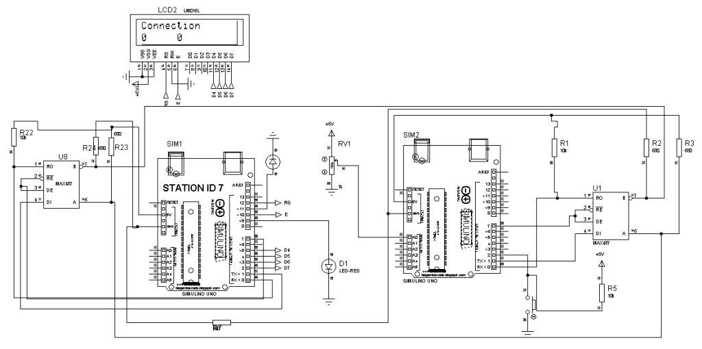
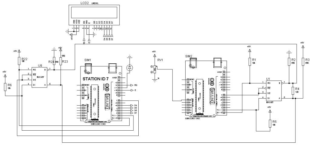
I have been working on MODMUS RTU communication between two Arduino Uno One arduino unso as Master and other is Slave. I am using [SimpleModbusMaste.h Rev2] and [SimpleModbusSlave V10] and RS487 as serial communication chip but I am getting OUTPUT only 0.

Here my code for master

//#include <Wire.h>
#include <SimpleModbusMaster.h>
#include <LiquidCrystal.h>


/*
   The example will use packet1 to read a register from address 0 (the adc ch0 value)
   from the arduino slave (id=1). It will then use this value to adjust the brightness
   of an led on pin 9 using PWM.
   It will then use packet2 to write a register (its own adc ch0 value) to address 1 
   on the arduino slave (id=1) adjusting the brightness of an led on pin 9 using PWM.
*/

//////////////////// Port information ///////////////////
#define baud 9600
#define timeout 2000
#define polling 400 // the scan rate
#define retry_count 20

// used to toggle the receive/transmit pin on the driver
#define TxEnablePin 7 
#define SlaveID 1
#define LED 11
#define LED1 9

// The total amount of available memory on the master to store data
#define TOTAL_NO_OF_REGISTERS 2
LiquidCrystal lcd(12, 10, 5, 4, 3, 2);
// This is the easiest way to create new packets
// Add as many as you want. TOTAL_NO_OF_PACKETS
// is automatically updated.
enum
{
  PACKET1,
  PACKET2,
  TOTAL_NO_OF_PACKETS // leave this last entry
};
// Create an array of Packets to be configured
Packet packets[TOTAL_NO_OF_PACKETS];

// Masters register array
unsigned int regs[TOTAL_NO_OF_REGISTERS];

void setup()
{
  //Serial.begin(115200);
  lcd.begin(16, 2);
  // Initialize each packet
  modbus_construct(&packets[PACKET1], 1, READ_HOLDING_REGISTERS, 0, 1, regs); //(packet,SlaveId,Function,holdingregAdress,data,locanstartadress)
  modbus_construct(&packets[PACKET2], 1,  READ_HOLDING_REGISTERS, 1, 1, regs);
  
  // Initialize the Modbus Finite State Machine
  modbus_configure(&Serial, baud, SERIAL_8N2, timeout, polling, retry_count, TxEnablePin, packets, TOTAL_NO_OF_PACKETS, regs);
  
  pinMode(LED, OUTPUT);
  pinMode(LED1, OUTPUT);
}

void loop()
{
  lcd.setCursor(0, 0);
  //lcd.print("MODBUS RTU");
  modbus_update();
  if (Serial.available()>0)
  {
  lcd.print("Connection");
  //regs[1] = analogRead(A0); // update data to be written to arduino slave
  analogWrite(LED, regs[0]/4);// constrain adc value from the arduino slave to 255
  lcd.setCursor(0, 1);
  lcd.print(regs[0]);
  digitalWrite(LED1,regs[1]);
  lcd.setCursor(6, 1);
  lcd.print(regs[1]);
}}

and code for Slave

#include <SimpleModbusSlave.h>

/* 
   SimpleModbusSlaveV10 supports function 3, 6 & 16.
   
   This example code will receive the adc ch0 value from the arduino master. 
   It will then use this value to adjust the brightness of the led on pin 9.
   The value received from the master will be stored in address 1 in its own
   address space namely holdingRegs[].
   
   In addition to this the slaves own adc ch0 value will be stored in 
   address 0 in its own address space holdingRegs[] for the master to
   be read. The master will use this value to alter the brightness of its
   own led connected to pin 9.
   
   The modbus_update() method updates the holdingRegs register array and checks
   communication.

   Note:  
   The Arduino serial ring buffer is 64 bytes or 32 registers.
   Most of the time you will connect the arduino to a master via serial
   using a MAX485 or similar.
 
   In a function 3 request the master will attempt to read from your
   slave and since 5 bytes is already used for ID, FUNCTION, NO OF BYTES
   and two BYTES CRC the master can only request 58 bytes or 29 registers.
 
   In a function 16 request the master will attempt to write to your 
   slave and since a 9 bytes is already used for ID, FUNCTION, ADDRESS, 
   NO OF REGISTERS, NO OF BYTES and two BYTES CRC the master can only write
   54 bytes or 27 registers.
 
   Using a USB to Serial converter the maximum bytes you can send is 
   limited to its internal buffer which differs between manufactures. 
*/

#define baud 9600
#define TxEnablePin 7 
#define SlaveID 1
#define button 2
#define analog A0
// Using the enum instruction allows for an easy method for adding and 
// removing registers. Doing it this way saves you #defining the size 
// of your slaves register array each time you want to add more registers
// and at a glimpse informs you of your slaves register layout.

//////////////// registers of your slave ///////////////////
enum 
{     
  // just add or remove registers and your good to go...
  // The first register starts at address 0
  ADC_VAL,     
  DIG_VAL,        
  HOLDING_REGS_SIZE // leave this one
  // total number of registers for function 3 and 16 share the same register array
  // i.e. the same address space
};

unsigned int holdingRegs[HOLDING_REGS_SIZE]; // function 3 and 16 register array
////////////////////////////////////////////////////////////

void setup()
{
  //Serial.begin(9600);
  /*parameters(HardwareSerial* SerialPort,
                long baudrate, 
 unsigned char byteFormat,
                unsigned char ID, 
                unsigned char transmit enable pin, 
                unsigned int holding registers size,
                unsigned int* holding register array)
  */
  
  /* Valid modbus byte formats are:
     SERIAL_8N2: 1 start bit, 8 data bits, 2 stop bits
     SERIAL_8E1: 1 start bit, 8 data bits, 1 Even parity bit, 1 stop bit
     SERIAL_8O1: 1 start bit, 8 data bits, 1 Odd parity bit, 1 stop bit
     
     You can obviously use SERIAL_8N1 but this does not adhere to the
     Modbus specifications. That said, I have tested the SERIAL_8N1 option 
     on various commercial masters and slaves that were suppose to adhere
     to this specification and was always able to communicate... Go figure.
     
     These byte formats are already defined in the Arduino global name space. 
  */
 
  modbus_configure(&Serial,baud, SERIAL_8N2,SlaveID, TxEnablePin ,HOLDING_REGS_SIZE, holdingRegs);

  // modbus_update_comms(baud, byteFormat, id) is not needed but allows for easy update of the
  // port variables and slave id dynamically in any function.
  //modbus_update_comms(9600, SERIAL_8N2, 1);
  
  pinMode(button, INPUT);
}

void loop()
{
  // modbus_update() is the only method used in loop(). It returns the total error
  // count since the slave started. You don't have to use it but it's useful
  // for fault finding by the modbus master.
  
  modbus_update();
  
  holdingRegs[ADC_VAL] = analogRead(A0); // update data to be read by the master to adjust the PWM
  holdingRegs[DIG_VAL] = digitalRead(button); 
  //analogWrite(LED, holdingRegs[1]/4); // constrain adc value from the arduino master to 255
  
  /* Note:
     The use of the enum instruction is not needed. You could set a maximum allowable
     size for holdinRegs[] by defining HOLDING_REGS_SIZE using a constant and then access 
     holdingRegs[] by "Index" addressing. 
     I.e.
     holdingRegs[0] = analogRead(A0);
     analogWrite(LED, holdingRegs[1]/4);
  */
  
}

I have tried in these two way but I didn't get any output..

Sorry, my answer was pointless ! I erased it.

hello folks,
Is possible to use this Modbus RTU master library with software serial?
What modification need to be done to get that working?
I tried this bellow but I got some errors.

SoftwareSerial mySerial(2, 3);
modbus_configure(&mySerial, baud, SERIAL_8N2, timeout, polling, retry_count, TxEnablePin, packets, TOTAL_NO_OF_PACKETS, regs);

Another question just in case anyone knows... I tested the Modbus library GitHub - 4-20ma/ModbusMaster: Enlighten your Arduino to be a Modbus master and it work fine for me with arduino using the software serial, leaving the hardware serial port for debug.
I tried that same library with the ESP8266 and it works.. the problem is if i disconnect the RS485 cable from the slave then ESP8266 crash..after a few intent of read modbus, not sure if its valid ask for advice just right here about ESP8266.
thanks for any help

Hi XVrs,

Im a Newbie,

Does the code you posted work on Arduino uno?
Im trying to read Power from a Inepro Metering PRO380-Mod.

Here is the link for the registers.
http://www.ineprometering.com/images/pdf/manuals/new//PRO380-Modbus-registers.pdf

Here is the Manual.
http://www.ineprometering.com/images/pdf/manuals/new//PRO380-user-manual.pdf

How should the code be setup to be able to read from any register?

The PRO380-Mod can be connected for Modbus communication. The Modbus implementation used is
Modbus basic (standard). This means the following:
 Baud rate 9600 bits/sec
 8 data bits
 even parity
 1 stop bit
The following values can be set; 9600, 4800, 2400, 1200, 600 and 300
Parity can be set to even or none.

Thank you for your time, hope to hear if this can be done.

someone pls help in finding a program for "energy meter monitoring over internet of things".i am usng rs485 shield converter and wifi shield(esp8266).

Hi timk__,

Read your post about using multiple packets. I have been trying to use a single packet to ON/OFF and increase or decrease speed of the Drive. Since a single packet responds to your requirement, I would like to throw this question.

You have used the following line in your code:
modbus_construct(&packets[PACKET1], 1, READ_HOLDING_REGISTERS, 4096, 21, 0);

Can you please explain the reason for using 4096,21,0? In some websites it refers to the address, data, local_address respectively.

I have to control a drive using the Modbus RTU protocol. I am using holding registers to write the data to turn the drive ON/OFF. Can you suggest me how the modbus_construct line should be used to suit my requirement?
Address:50000 Data:0x043C(ON) Slave ID:01

I tried converting hex to decimal and put 0 in the place of the Local_address. It hasn't responded.
Any Help would be highly appreciated. :slight_smile:

hello JuanB,
do u know how can i send data in hex format using modbus protocol ? also is there a guide for every function funcitionality ? how can i use modbus if my master is pc (using matlab to program it) or how to use modbusmat 1.1 simulator ?
thank you

Hello all,
Now I have problem to apply simplemodbus to communicating
between Genuino101 master and PLC slave.

However, lots of compile error came out and I could not understand
why such error occur.

Could you give me any advice??

The error messages are as below.


Arduino:1.8.2 (Windows 7), ボード:"Arduino/Genuino 101"

sketch\SimpleModbusMaster.cpp: In function 'void modbus_configure(HardwareSerial*, long int, unsigned char, long int, long int, unsigned char, unsigned char, Packet*, unsigned int, unsigned int*)':

SimpleModbusMaster.cpp:452: error: no matching function for call to 'HardwareSerial::begin(long int&, unsigned char&)'

(*ModbusPort).begin(baud, byteFormat);

^

sketch\SimpleModbusMaster.cpp:452:38: note: candidate is:

In file included from C:\Users\take\AppData\Local\Arduino15\packages\Intel\hardware\arc32\2.0.2\cores\arduino/Arduino.h:111:0,

from C:\Users\take\AppData\Local\Arduino15\packages\Intel\hardware\arc32\2.0.2\libraries\CurieSoftwareSerial\src/SoftwareSerial.h:30,

from sketch\SimpleModbusMaster.cpp:1:

C:\Users\take\AppData\Local\Arduino15\packages\Intel\hardware\arc32\2.0.2\cores\arduino/HardwareSerial.h:29:18: note: virtual void HardwareSerial::begin(long unsigned int)

virtual void begin(unsigned long) = 0;

^

C:\Users\take\AppData\Local\Arduino15\packages\Intel\hardware\arc32\2.0.2\cores\arduino/HardwareSerial.h:29:18: note: candidate expects 1 argument, 2 provided

exit status 1
no matching function for call to 'HardwareSerial::begin(long int&, unsigned char&)'


Hello sir,

i'm also trying to get energy meter reading data on arduino, i have tried code but its giving me error on "modbus_construct" instruction
could you plz help me

Hello Everybody
I am trying 20 numbers arduino uno communicate with HMI on RS 485 using modbus RTU . I am very New to used modbus RTU , I am just trying one UNO and HMI using MAX485 using Simple Modbus Library , but confused wheater arduino uno is Master or Slave
I want only to write two timer values in UNO by HMI

hello i'm working on em6436 meter

im using simple modbus master library, and i'm getting zero output, could anyone please help me.

i have attached code and output of command window

slave parameters:
id=2
baud rate=9600
address=3091
parity= No 1
also i have attached pullup and pulldown resistors to A and B in max 485 module

#include <SimpleModbusMaster.h>

/*
   The example will use packet1 to read a register from address 0 (the adc ch0 value)
   from the arduino slave (id=1). It will then use this value to adjust the brightness
   of an led on pin 9 using PWM.
   It will then use packet2 to write a register (its own adc ch0 value) to address 1 
   on the arduino slave (id=1) adjusting the brightness of an led on pin 9 using PWM.
*/

//////////////////// Port information ///////////////////
#define baud 9600
#define timeout 1000
#define polling 400 // the scan rate
#define retry_count 10

// used to toggle the receive/transmit pin on the driver
#define TxEnablePin 2

#define LED 9

// The total amount of available memory on the master to store data
#define TOTAL_NO_OF_REGISTERS 12

// This is the easiest way to create new packets
// Add as many as you want. TOTAL_NO_OF_PACKETS
// is automatically updated.
enum
{
  PACKET1,
 // PACKET2,
  TOTAL_NO_OF_PACKETS // leave this last entry
};

// Create an array of Packets to be configured
Packet packets[TOTAL_NO_OF_PACKETS];

// Masters register array
unsigned int regs[TOTAL_NO_OF_REGISTERS];

void setup()
{
  // Initialize each packet
//  Serial1.begin(9600);
  Serial.begin(9600);
  modbus_construct(&packets[PACKET1], 2, READ_HOLDING_REGISTERS, 1, 10);
 // modbus_construct(&packets[PACKET2], 1, PRESET_MULTIPLE_REGISTERS, 1, 1, 0);
  
  // Initialize the Modbus Finite State Machine
  modbus_configure(&Serial, baud, SERIAL_8N1, timeout, polling, retry_count, TxEnablePin, packets, TOTAL_NO_OF_PACKETS, regs);
  
  
}

void loop()
{
modbus_update();

  
  unsigned long temp;

  float Voltage;
  temp = (unsigned long) regs[10] << 16 | regs[11];
  Voltage = *(float*)&temp;
  Serial.println("test");
  Serial.println(Voltage, 1);

  Serial.print("requests: ");
    Serial.println(packets[PACKET1].requests);
    Serial.print("successful_requests: ");
    Serial.println(packets[PACKET1].successful_requests);
    Serial.print("failed_requests: ");
    Serial.println(packets[PACKET1].failed_requests);
    Serial.print("exception_errors: ");
    Serial.println(packets[PACKET1].exception_errors);
    Serial.print("connection: ");
    Serial.println(packets[PACKET1].connection);
  delay(5000);
}

output

test
0.0
requests: 2
successful_requests: 0
failed_requests: 2
exception_errors: 0
connection: 1
test
0.0
requests: 2
successful_requests: 0
failed_requests: 2
exception_errors: 0
connection: 1

I have been working with this Simple modbus library. Im successful in implementing function 16 that is to preset multiple registers. Now i have been trying for Read holding Registers that is function 3..But Im facing problem in implementing this feature in arduino. I couldnt read from slave .. I have even attached terminal resistors between the terminals A and B.. But still couldnt retrieve the data from slave.. in Slave arduino i can see the Rx and Tx leds blink but in master only Tx led is blinking.. Where M'i going wrong kindly help me..