Help with ModBus RTU Master-Slave: SimpleModbus [SOLVED]

Hello everyone....

i'm newbie to arduino

i'm having an ELMEASURE LG+1129 meter , i have been trying for several days to read the register values..

My Hardware: Arduino uno, RS-485

My Firmware: Arduino ide 1.8.3, simplemodbusmaster v2rev2 DUE

Can you please guide me how to read the register value from the ELMEASURE using arduino uno

My library:

https://drive.google.com/drive/folders/0B0B286tJkafVYnBhNGo4N3poQ2c

below here attached my connection dig, elmeasure lg 1129 datasheet

Elmeasure.pdf (492 KB)

Hello
I'm having trouble with the arduino Mega with the delay in reading modbus.
After some modifications I discovered that the delay is related to the number of packages.
Is there any way to read more than one value in a single package, as it should be.
This my code will increase twice, today to only update these values ​​below, delay 3 minutes

#include <SimpleModbusMaster.h>

/*
   The example will use packet1 to read a register from address 0 (the adc ch0 value)
   from the arduino slave (id=1). It will then use this value to adjust the brightness
   of an led on pin 9 using PWM.
   It will then use packet2 to write a register (its own adc ch0 value) to address 1 
   on the arduino slave (id=1) adjusting the brightness of an led on pin 9 using PWM.
*/

long previousMillis = 0;
long interval = 1000;

//////////////////// Port information ///////////////////
#define baud 9600
#define timeout 1000
#define polling 200 // the scan rate
#define retry_count 10

// used to toggle the receive/transmit pin on the driver
#define TxEnablePin 10

#define LED 9

// The total amount of available memory on the master to store data
#define TOTAL_NO_OF_REGISTERS 23

// This is the easiest way to create new packets
// Add as many as you want. TOTAL_NO_OF_PACKETS
// is automatically updated.
enum
{
  READ_FROM_SLAVE_1,       // Letter 0
  PACKET1,
  PACKET2,
  PACKET3,
  PACKET4,
  PACKET5,
  PACKET6,
  PACKET7,
  PACKET8,
  PACKET9,
  PACKET10,
  PACKET11,
  PACKET12,
  PACKET13,
  PACKET14,
  PACKET15,
  PACKET16,
  PACKET17,
  PACKET18,
  PACKET19,
  PACKET20,
  PACKET21,
  PACKET22,
  PACKET23,
  TOTAL_NO_OF_PACKETS // leave this last entry
};

// Create an array of Packets to be configured
Packet packets[TOTAL_NO_OF_PACKETS];

// Masters register array
unsigned int regs[TOTAL_NO_OF_REGISTERS];
unsigned int readRegs[1];
unsigned long currentMillis;

void setup()
{
  Serial.begin(9600);
  // Initialize each packet


  modbus_construct(&packets[PACKET1], 1, READ_HOLDING_REGISTERS, 0, 1, 0);
  modbus_construct(&packets[PACKET2], 1, READ_HOLDING_REGISTERS, 1, 1, 1);
  modbus_construct(&packets[PACKET3], 1, READ_HOLDING_REGISTERS, 2, 1, 2);
  modbus_construct(&packets[PACKET4], 1, READ_HOLDING_REGISTERS, 3, 1, 3);
  modbus_construct(&packets[PACKET5], 1, READ_HOLDING_REGISTERS, 4, 1, 4);
  modbus_construct(&packets[PACKET6], 1, READ_HOLDING_REGISTERS, 5, 2, 5);
  modbus_construct(&packets[PACKET7], 1, READ_HOLDING_REGISTERS, 6, 2, 6);
  modbus_construct(&packets[PACKET8], 1, READ_HOLDING_REGISTERS, 7, 2, 7);
  modbus_construct(&packets[PACKET9], 1, READ_HOLDING_REGISTERS, 8, 1, 8);
  modbus_construct(&packets[PACKET10], 1,READ_INPUT_REGISTERS, 29, 1, 9); // Frequencia Rede
  modbus_construct(&packets[PACKET11], 1,READ_INPUT_REGISTERS, 700, 4,10); // Tensão Rede R+N
  modbus_construct(&packets[PACKET12], 1,READ_INPUT_REGISTERS, 702, 4, 11); // Tensão Rede S+N
  modbus_construct(&packets[PACKET13], 1,READ_INPUT_REGISTERS, 704, 4, 12); // Tensão Rede T+N
  modbus_construct(&packets[PACKET14], 1,READ_INPUT_REGISTERS, 28, 1, 13); // Frequencia Gerador
  modbus_construct(&packets[PACKET15], 1,READ_INPUT_REGISTERS, 708, 1, 14); // Tensão Gerador R+N
  modbus_construct(&packets[PACKET16], 1,READ_INPUT_REGISTERS, 710, 1, 15); // Tensão Gerador S+N
  modbus_construct(&packets[PACKET17], 1,READ_INPUT_REGISTERS, 712, 1, 16); // Tensão Gerador T+N
  modbus_construct(&packets[PACKET18], 1,READ_INPUT_REGISTERS, 72, 1, 17); // Tensão Bateria;
  modbus_construct(&packets[PACKET19], 1,READ_INPUT_REGISTERS, 70, 1, 18); // Horas Funcionamento Motor
  modbus_construct(&packets[PACKET20], 1,READ_INPUT_REGISTERS, 131, 1, 19); // Estado Motor
  modbus_construct(&packets[PACKET21], 1,READ_INPUT_REGISTERS, 720, 1, 20); // Horas manutenção
  modbus_construct(&packets[PACKET22], 1,READ_INPUT_REGISTERS, 120, 1, 21); // Modo de Operação
  modbus_construct(&packets[PACKET23], 1,READ_INPUT_REGISTERS, 130, 1, 22); // Alarme Status
  
  // Initialize the Modbus Finite State Machine
modbus_configure(&Serial1, baud, SERIAL_8N2, timeout, polling, retry_count, TxEnablePin, packets, TOTAL_NO_OF_PACKETS, regs);
  
  pinMode(LED, OUTPUT); 
}

void loop()
{
   modbus_update();
float Power;
  unsigned long temp = (unsigned long)regs[0] << 16 | regs[1];
  Power = *(float*)&temp;
  
   currentMillis = millis();
  if (currentMillis - previousMillis >= interval)
  {

    Serial.print("Exception errors: ");
    Serial.println(packets[PACKET1].exception_errors);

    Serial.print("Failed requests: ");
    Serial.println(packets[PACKET1].failed_requests);
    
    Serial.print("Successful requests: ");
    Serial.println(packets[PACKET1].successful_requests);
    Serial.print("Low byte: ");
    Serial.println(regs[0]);
    Serial.print("High byte: ");
    Serial.println(regs[1]);
    Serial.print("Power ");
    Serial.print(Power);
    Serial.println("----------");
  }
  
  Serial.print("Horário = ");
  Serial.print(regs[2]);
  Serial.print(":");
  Serial.print(regs[1]);
  Serial.print(":");
  Serial.print(regs[0]);
  Serial.println();
  /////////////////////////////////////////////////////////////////////
 Serial.print("Data = ");
  Serial.print(regs[3]);
  Serial.print("/");
  Serial.print(regs[5]);
  Serial.print("/");
  Serial.println(regs[6]);
  Serial.println();
  /////////////////////////////////////////////////////////////////////
  Serial.print("Frequência da Rede = ");
  Serial.print(regs[9]/255);
  Serial.print("Hz");
  Serial.println();
  /////////////////////////////////////////////////////////////////////
  Serial.print("Tensão da Rede = ");
  Serial.print("RN:");
  Serial.print(regs[10]/256);
  Serial.print("V, ");
  Serial.print("SN:");
  Serial.print(regs[11]/256);
  Serial.print("V, ");
  Serial.print("TN:");
  Serial.print(regs[12]/256);
  Serial.print("V");
  Serial.println();
  /////////////////////////////////////////////////////////////////////
  Serial.print("Frequência do Gerador = ");
  Serial.print(regs[13]/255);
  Serial.print("Hz");
  Serial.println();
  /////////////////////////////////////////////////////////////////////
  Serial.print("Tensão do Gerador = ");
  Serial.print("RN:");
  Serial.print(regs[14]/256);
  Serial.print("V, ");
  Serial.print("SN:");
  Serial.print(regs[15]/256);
  Serial.print("V, ");
  Serial.print("TN:");
  Serial.print(regs[16]/256);
  Serial.print("V");
  Serial.println();
  /////////////////////////////////////////////////////////////////////
  Serial.print("Tensão da Bateria = ");
  Serial.print(regs[17]/256);
  Serial.print("VCC");
  Serial.println();
  /////////////////////////////////////////////////////////////////////
  Serial.print("Horas Funcionamento = ");
  Serial.print(regs[18]);
  Serial.print("h");
  Serial.println();
  /////////////////////////////////////////////////////////////////////
 Serial.print("Status = ");
  if (regs[19] == 0)
{
  Serial.print("Parando");
}
  if (regs[19] == 1)
{
  Serial.print("Abortar Parada");
}
  if (regs[19] == 2)
{
  Serial.print("Parado");
}
  if (regs[19] == 3)
{
  Serial.print("Falha na Parada");
}
Serial.println();
/////////////////////////////////////////////////////////////////////
Serial.print("Manutenção = ");
Serial.print(regs[20]);
Serial.print("h");
Serial.println();
/////////////////////////////////////////////////////////////////////
Serial.print("Modo = ");
  if (regs[21] == 0)
{
  Serial.print("OFF");
}
  if (regs[21] == 1)
{
  Serial.print("MANUAL");
}
  if (regs[21] == 2)
{
  Serial.print("AUTOMÁTICO");
}
  if (regs[21] == 3)
{
  Serial.print("TEST");
}
  if (regs[21] == 4)
{
  Serial.print("REMOTE START");
}
Serial.println();
/////////////////////////////////////////////////////////////////////
  delay(100);
}

you can read more than one byte per packet. This will spare at least your first 6 Packets from your current example.
I follow this logic

modbus_construct(&packets[PACKET0], 1, READ_INPUT_REGISTERS, 0xStartadress, BytesToReads, FirstRegisterIndex);

in your case
modbus_construct(&packets[PACKET1], 1, READ_HOLDING_REGISTERS, 0, 5, 0);
will do the same like your first 5 rows.

This makes no sense for me

modbus_construct(&packets[PACKET6], 1, READ_HOLDING_REGISTERS, 5, 2, 5);
modbus_construct(&packets[PACKET7], 1, READ_HOLDING_REGISTERS, 6, 2, 6);
modbus_construct(&packets[PACKET8], 1, READ_HOLDING_REGISTERS, 7, 2, 7);

PACKET6 will write in data and sets Register 5 and 6, because you are requesting 2 bytes.
PACKET7 will read again data and sets Register 6 and 7 ...
PACKET8 will read data and sets Register 7 and 8

so you are reading byte 6 and 7 two times.

try to reduce the packets but without exceeding the internal buffers.

Thank you,
It worked correctly.
I tried several ways but I could not.

I need more help:
What better method to read and write a value in BIT, since the reading is DECIMAL.
Example:

Bit00 Alarm
Bit01 Shutdow
Bit02 Reset
.
.
Exemple supervisory Set Driver1.Tag1.Bit02 = true.

In the arduino how would it be?

I do not see that being a problem for a Modbus master.

In the past I have used this technique in a GNU/Linux based program I developed using Libmodbus library, where multiple slaves were polled on different communications channels at user defined rates. The master would go out to poll the slave for all packets in sequence with short inter packet polling delays and then wait for the user defined period before starting the packet sequence again.

You should be able to do the same with Arduino based libraries to I imagine.


Paul - VK7KPA

I'm pretty sure it can be done, but the question is, if it was already done by someone with that particular library. Yes I can stop the requests by something like

packets[i].connection = false;

but i would like to know what's the best solution to disconnect after one (sucessfull) cycle and reconnect all packets again after a certain periode of time...

My project involves controlling actuators and reading position data from them. I am using SMBmaster and SMBslave on Mega 2560's. I am using Linksprite RS485 shields that I have modified in order to easily route the hardware TX and RX pins to SERIAL1 pins (18 and 19) on the Mega 2560. From a hardware and software perspective, I have things up and running pretty well. So this isn't a request for how to get one thing or another working. The following may sound like a stupid question, but I will risk it.

In operation, the master controls a device with position pots and motors. The master (remote controller) polls the slave to get current position data, which it then displays for the user. The user then changes the positioning on slave device, the new position is shown on the display prior to the "move" command being transmitted from the master to the display. When the modbus_update() is executed, two packets go out (position readout update request, and the move command) and the position is read by the slave and transmitted back to the master, before the move command has completed. As a result, the display might read 10.0 inches (the new position specified), then flash to 7.1 inches, 9.9 inches and then settle on 10.0. I've developed a work around, but..

The question is: can packets be "suppressed", or once enumerated and constructed, all packets go out with every modbus_update()?

In reading the 100's of posts in this thread, I've not seen this discussed, though I might have missed it. Given the PLC roots of modbus, I would think a PLC controls its modbus requests as it sees fit. Is it possible to reconfigure a "constructed" packet on the fly? I can see several ways around this, but I am wondering if I am missing something obvious.

Thanks, John

Hey ModBus Experts,

I just have one question. I keep getting exception errors when i try to communicate with my ELMeasure LG+ 5310 series energy meter. The communication light blinks as many times as i given the retry count. But I get no reply. If anyone has any answer, it will be highly appreciated. :smiley:

I'm pasting the code here.

#include <SimpleModbusMaster.h>


//////////////////// Port information ///////////////////
#define baud 9600
#define timeout 1000
#define polling 500 // the scan rate
#define retry_count 10

// used to toggle the receive/transmit pin on the driver
#define TxEnablePin 2 

// The total amount of available memory on the master to store data
#define TOTAL_NO_OF_REGISTERS 2

// This is the easiest way to create new packets
// Add as many as you want. TOTAL_NO_OF_PACKETS
// is automatically updated.
enum
{
  PACKET1,
  TOTAL_NO_OF_PACKETS // leave this last entry
};

// Create an array of Packets to be configured
Packet packets[TOTAL_NO_OF_PACKETS];

// Masters register array
unsigned int regs[TOTAL_NO_OF_REGISTERS];

void setup()
{

 // Initialize each packet
  modbus_construct(&packets[PACKET1], 1, READ_HOLDING_REGISTERS, 40101, 2, 0);
 Serial.begin(9600);
  // Initialize the Modbus Finite State Machine
  modbus_configure(&Serial1, baud, SERIAL_8E2, timeout, polling, retry_count, TxEnablePin, packets, TOTAL_NO_OF_PACKETS, regs);
  
}

void loop()
{

    modbus_update();
    Serial.print(packets[PACKET1].requests);
    Serial.print(";successful_requests: ");  
    Serial.print(packets[PACKET1].successful_requests);
    Serial.print(";failed_requests: ");  
    Serial.print(packets[PACKET1].failed_requests);  
    Serial.print(";exception_errors: ");  
    Serial.print(packets[PACKET1].exception_errors); 
    Serial.println(regs[0]);
    Serial.println(regs[1]);
}

If anyone wants to see the register map, its here Register Map

Thank you much.

@John, you can try following:

packets[i].connection = false;

where i is the the packet to deactivat

I use it vice versa: I try to reconnect each slave every hour just in case it was deactived, so the other way round should work also ...

@VarunNelakanti

I assume you have got a wrong adress:

  modbus_construct(&packets[PACKET1], 1, READ_HOLDING_REGISTERS, 40101, 2, 0);

Read the very good manual of the library and see how to start counting with READ_HOLDING_REGISTERS.
I assume 40101 is to high as you should just use a offest to the start where RED_HOLDING_REGISTERS usually start, but that should be found in the manual.

Just as a hint, I'm using READ_INPUT_REGISTERS, and have only to add 0x3100 ... so 40101 looks very high to me:

modbus_construct(&packets[PACKET0], 1, READ_INPUT_REGISTERS, 0x3100, 8, 0);

From page 28 of the product manual:
4. If RS-485 communication does not work:
a) Check that the baud rate of the host computer/PLC is the same as Meter.
b) Check that the device ID of the meter are unique and should not replicate.
c) Check all communications wiring is complete.
d) Check that the number of data bits is set to 8, with one stop bit and even
parity.

Also Page 8 tells you where the display value of the device ID

You are not showing your resulting printout, which might be helpful. And it is not clear that you have checked other aspects of your setup, such as match the slave ID to what you have declared in your program.

noiasca:
@John, you can try following:

packets[i].connection = false;

where i is the the packet to deactivat

I use it vice versa: I try to reconnect each slave every hour just in case it was deactived, so the other way round should work also ...

Noiasca,

Thank you very much, that does the trick.

-John

Following up on what noiasca stated, I think that "READ_HOLDING_REGISTERS" automatically generates the 40001 "base address", therefore you don't need to state it explicitly, I think that replacing the the 40101 with either 100 or 101 gets you to that address on the device.

 // Initialize each packet
  modbus_construct(&packets[PACKET1], 1, READ_HOLDING_REGISTERS, 40101, 2, 0);
 Serial.begin(9600);
  // Initialize the Modbus Finite State Machine
  modbus_configure(&Serial1, baud, SERIAL_8E2, timeout, polling, retry_count, TxEnablePin, packets, TOTAL_NO_OF_PACKETS, regs);
  
}

I can not understand what's going on with my communication.
It works and then stops and no more comes back to communication.
I've been looking for an answer for two days, but I can not find it.
After the communication drops the first time even I sending another program it does not come back.
can anybody help me?

after how many successfull requests does your device stop?
And have you read the manual - they don't recommend software serial for modbus.

hi everyone
i am working on a project in which i have to fetch data from LT wl4400 multifunction meter using rs485 and arduino uno R3.i gone through all the previous posts on this topic. i really need help to find what is the problem in code?
here i am attaching my code ...please help me out ...

#include <SimpleModbusMaster.h>

#define baud 9600
#define timeout 1000
#define polling 200 // the scan rate
#define retry_count 10
#define TOTAL_NO_OF_REGISTERS 13
#define TxEnablePin 4
enum
{
PACKET1,
PACKET2,
TOTAL_NO_OF_PACKETS

};

Packet packets[TOTAL_NO_OF_PACKETS];
unsigned int regs[TOTAL_NO_OF_REGISTERS];

/long previousMillis = 0;
long interval = 1200;
unsigned long currentMillis;
int good_count = 0;
/

void setup()
{
pinMode(TxEnablePin,OUTPUT);
Serial.begin(9600);

digitalWrite(TxEnablePin,HIGH);

modbus_construct(&packets[PACKET1], 1, READ_HOLDING_REGISTERS, 0137,1,10);
// modbus_construct(&packets[PACKET1], 1, READ_HOLDING_REGISTERS, 0139,1,11);
modbus_construct(&packets[PACKET1], 1, READ_HOLDING_REGISTERS, 0157,1,12);

modbus_construct(&packets[PACKET2], 1, PRESET_MULTIPLE_REGISTERS, 1, 1, 0 );

modbus_configure(&Serial, baud, SERIAL_8E1, timeout, polling, retry_count, TxEnablePin, packets, TOTAL_NO_OF_PACKETS, regs);
pinMode(TxEnablePin,OUTPUT);

}

void loop()
{

digitalWrite(TxEnablePin,HIGH);

modbus_update();
unsigned long temp;
float voltage, voltage1,voltage2;
//temp = (unsigned long) regs[1] << 16|regs[0];
voltage = regs[10];
voltage = regs[11];
voltage = regs[12];
Serial.print("voltage:");

Serial.println(voltage);
Serial.print("voltage1:");

Serial.println(voltage1);
Serial.print("voltage2:");

Serial.println(voltage2);

delay(1000);
}

What do you expect?
What does your code?
Describe clearly what's wrong. We do not have your hardware so we just see some code!

From the code I see:
pinMode in row 45 should do what?

you are declaring in row 11/12 PACKET1, PACKET2

starting with with 35 you try to use
PACKET0,
two times PACKET1
PACKET2

I guess the value at adress 0137 will never find the way into register 10

And check the value of the startadresses, are they really correct. Please provide a datasheet of your device.

in other words: throw away your code and start from scratch.
Take the example and change only the two exisiting packets to your needs as a starting point.
Add only two Serial.prints to print out two registers.

When you get reliable results, enrich the code.

Hi, I have built an Arduino Nano based MODBUS datalogger and I have one remaining strange bug someone might be able to shed some light on.

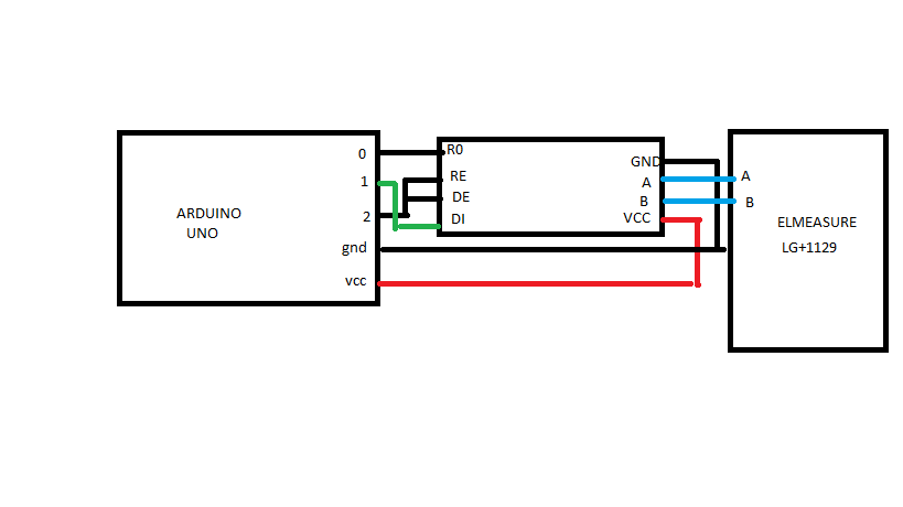
I am using the SimpleModbusMasterV2rev2 library, an RS485 to TTL adaptor wired to digital pins 0, 1 and 2 (with DE and RE both tied to D2) and a Hitachi hd44780 16x2 character LCD on pins 3 to 9. (there is also an SD card interface wired to the SPI inteface (D10-13), some buttons wired between A0 and +5V with series resistors, LEDs between pins A1-A3 and ground with series resistors and real time clock on the I2C interface (A4-A5), these are still connected but I have created a stripped down version of my code omitting everything except the MODBUS comms and output to the LCD). I am reading an ABB B21 electric meter and for testing am reading the least signifcant parts of the energy, voltage, current and frequency registers.

I was originally testing with a baud rate of 9600 and 8E1 Data/Parity/Stop Bits. I was reading 4 holding registers into a unsigned int array regs[], and expected them to be in regs[0] to regs[3], but when I retrieved them they are offset by one, with the result from the register defined in packet[0] returned in regs[1].. packet [2] in regs[3] and packet[3] in regs[0]

Then I started testing other baud rates and Data/Parity/Stop Bit settings and these change the array subscript the values are returned in, e.g. with 9600 and 8O1 the values are in the expected places in the array (regs[0] corresponding to packet[0] etc), with 9600 and 8N2 the result is as for 9600, 8E1

If I only have one packet defined the code always works as expected with regs[0] corresponding to packet[0] whatever the baud rate and Data/Parity/Stop Bit settings.

Here is my stripped down code. When I try interrogating different numbers of registers (let's call this n), I am changing
#define TOTAL_NO_OF_REGISTERS n
Commenting out the highest numbered modbus_construct calls as appropriate
Changing the penultimate parameter in the modbus_configure call to n
I am leaving the lcd.print commands and as one would expect they just print garbage when the array subscript exceeds the size of the array.

Further testing shows:
Values returned correctly with odd parity and 1200, 2400, 4800, 9600, 38400 or 5600 baud

Values in wrong order on odd parity with 19200 or 115200 baud, or 9600 to 115200 with even or no parity bit, no values returned at 1200, 2400 or 4800 baud if using even or no parity. Similar results with 1,3 or 4 packets (=registers) (except obviously if only one packet and register in use can't see the order problem, value is in subscript zero).

//___________________________________

//LIBRARIES
#include <LiquidCrystal.h> //LCD Library
#include <SimpleModbusMaster.h> //Modbus RTU

//DEFINITIONS to insert into code at compile time (so end up in flash memory not RAM)
//LCD Pins
#define pin_RS 8 //arduino pin wired to LCD RS
#define pin_EN 9 //arduino pin wired to LCD EN
#define pin_d4 4 //arduino pin wired to LCD d4
#define pin_d5 5 //arduino pin wired to LCD d5
#define pin_d6 6 //arduino pin wired to LCD d7
#define pin_d7 7 //arduino pin wired to LCD d8
#define pin_BL 3 //arduino pin wired to LCD backlight circuit

//Modbus
#define timeout 1000 //Maximum time for slave to respond (ms)
#define polling 2000 //Maximum scan rate of master to allow slave to return to idle (ms)
#define retry_count 10 //Maximum retries if slave returns response timeout or error
#define TxEnablePin 2 //Pin to set RS485 interface to transmit or receive (set pin high to Transmit, sets DE and RE on RS485 PCB high. DE must be high to transmit and RE low to receive)

//Misc
#define LongIntMax 4294967295 //Maximum value of a long integer, used in timer check in case value has reset to zero in the interval
#define LCD_UD_Int 900 //LCD Update Interval (ms). Should happen just over once a second so clock seconds increment nicely

//GLOBAL VARIABLES
unsigned long Prev_LCD_UD = 0; //Timer at last LCD update

#define TOTAL_NO_OF_REGISTERS 4 //Max number of registers to log, used to allocate memory, same as total packets as all packets are sized for one register

// Create an array of Packets to be configured
Packet packets[TOTAL_NO_OF_REGISTERS];

//Create an array to hold returned data in its raw form of unsigned integers
unsigned int holdingRegs[TOTAL_NO_OF_REGISTERS];

//INITIALISE DEVICES
LiquidCrystal lcd( pin_RS, pin_EN, pin_d4, pin_d5, pin_d6, pin_d7); //Initialise LCD

void setup()
{
// set up the LCD's number of columns and rows:
lcd.begin(16, 2);

// Initialise backlight
//BL_Timeout = Def_BL_Timeout; //Backlight timeout to default
digitalWrite(pin_BL, LOW); //Ensures pullup disabled to avoid damage due to backlight circuit bad design
pinMode(pin_BL, INPUT); //Set Backlight On

//Initialise RS485 Pin
pinMode(TxEnablePin, OUTPUT);
digitalWrite(TxEnablePin,LOW);//Receive 485

//Initialise modbus
modbus_construct(&packets[0], 6, READ_HOLDING_REGISTERS, 20483, 1, 0); //Energy
modbus_construct(&packets[1], 6, READ_HOLDING_REGISTERS, 23297, 1, 1); //Voltage
modbus_construct(&packets[2], 6, READ_HOLDING_REGISTERS, 23309, 1, 2); //Current
modbus_construct(&packets[3], 6, READ_HOLDING_REGISTERS, 23340, 1, 3); //Frequency
modbus_configure(&Serial, 9600, SERIAL_8E1, timeout, polling, retry_count, TxEnablePin, packets, 4 ,holdingRegs); //Changed from max allowable registers (TOTAL_NO_OF_REGISTERS) to actual (x)
}

void loop()
{
//Poll the MODBUS devices
modbus_update();

//Update the LCD periodically
if(Interval_Check(Prev_LCD_UD, LCD_UD_Int))
{
//Clear Display
lcd.clear(); //In case data not entirely erased by new data

//Write current values of up to 4 registers
lcd.setCursor(0,0); //LCD Column (0-15), row (0-1)
lcd.print(holdingRegs[0]);

lcd.setCursor(8,0);
lcd.print(holdingRegs[1]);

lcd.setCursor(0,1);
lcd.print(holdingRegs[2]);

lcd.setCursor(8,1);
lcd.print(holdingRegs[3]);

//Reset LCD refresh timer
Prev_LCD_UD=millis();
}
}

byte Interval_Check(unsigned long datum, unsigned long interval) //return 1 if interval has elapsed
{
unsigned long current_time = millis();
if ((current_time < datum) && (((LongIntMax - datum) + (current_time)) > interval))
{
return 1;
}
else if ((current_time < datum) && (((LongIntMax - datum) + (current_time)) <= interval))
{
return 0;
}
else if ((current_time - datum) > interval)
{
return 1;
}
else
{
return 0;
}
}

//________________________________________________________________

Any advice welcomed!
Andrew Mitchell
t.a.mitchell@ex.ac.uk

Good evening,
I am developing a monitoring system through an Arduino Mega master connected to a slave PLC.
Communication OK.
But I noticed in my application that when I used the PACKETS in sequence, the system collapsed, read out, lost connection, I discovered by chance that when I skip the PACKETS the values are read and there are no connection losses.

I ask you whether this is normal or what could be causing this?
The way the system works is to have a delay to carry out the entire reading of at least 20 seconds.
Can I, for example, decrease this time?

it might be not the problem you are looking for, but

you've defined
#define TOTAL_NO_OF_REGISTERS 30

but already in PACKET2 you are using

50);//Gerador Tensão

this last number is the register index where the first value will be copied

so check your

unsigned int regs[xx];

best, change it to

unsigned int regs[TOTAL_NO_OF_REGISTERS];