Hello,
I want to read data from a DC 1040 PID Controller, with my Arduino and I am using RS485-TTL module . I'am using a simple modbus master library it's default communication is :
Protocol: MOdBUS RTU
Baud Rate: 38400
Parity: ODD
Stop Bits: 1
Data Bits: 8
I want to read PV Value which is register 138.
this is my code....
#include <SimpleModbusMaster.h>
//////////////////// Port information ///////////////////
#define baud 38400
#define timeout 1000
#define polling 300 // the scan rate
#define retry_count 50
// used to toggle the receive/transmit pin on the driver
#define TxEnablePin 2
// The total amount of available memory on the master to store data
#define TOTAL_NO_OF_REGISTERS 13
// This is the easiest way to create new packets
// Add as many as you want. TOTAL_NO_OF_PACKETS
// is automatically updated.
enum
{
PACKET1,
PACKET2,
PACKET3,
PACKET4,
TOTAL_NO_OF_PACKETS // leave this last entry
};
// Create an array of Packets to be configured
Packet packets[TOTAL_NO_OF_PACKETS];
// Masters register array
unsigned int regs[TOTAL_NO_OF_REGISTERS];
void setup()
{
// Initialize each packet
Serial.begin(38400);
modbus_construct(&packets[PACKET1], 1, READ_HOLDING_REGISTERS,138, 1, 10);
// modbus_construct(&packets[PACKET2], 1, READ_HOLDING_REGISTERS, 0000, 1, 11);
//modbus_construct(&packets[PACKET4], 1, READ_HOLDING_REGISTERS, 1, 1, 12);
//modbus_construct(&packets[PACKET1], 1, PRESET_MULTIPLE_REGISTERS,1, 1,0);
// Initialize the Modbus Finite State Machine
modbus_configure(&Serial, baud, SERIAL_8O1, timeout, polling, retry_count, TxEnablePin, packets, TOTAL_NO_OF_PACKETS, regs);
}
void loop()
{
modbus_update();
float pv;
pv = regs[10];
delay(1000);
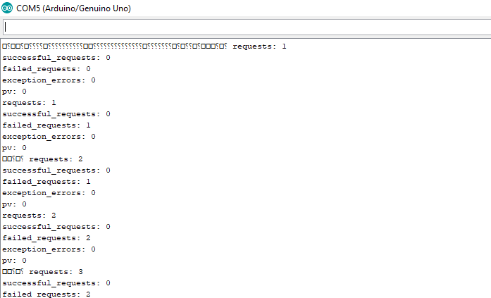
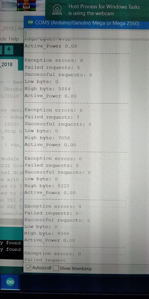
Serial.print("requests: ");
Serial.println(packets[PACKET1].requests);
Serial.print("successful_requests: ");
Serial.println(packets[PACKET1].successful_requests);
Serial.print("failed_requests: ");
Serial.println(packets[PACKET1].failed_requests);
Serial.print("exception_errors: ");
Serial.println(packets[PACKET1].exception_errors);
Serial.print("pv: ");
Serial.println(regs[10]);
}
The following attachment include connection made, datasheet, comm regs mapping,output

DC1040.pdf (855 KB)
COMMUNICATION MANUAL.pdf (380 KB)