Hi dgtldan,
I am a bit of a newbie to the Arduino community and am currently working or a project involving Modbus control for linear actuators.
First you should try to answer one question:
- which role is your Arduino going to perform in your network? Is it going to send orders and ask for states to the order network members? Is it going to play the same role as the other members?
As other industrial networks, MODBUS relies on one master and one or several slave devices. If your Arduino is going to control these other devices, then it would be a master. Otherwise, there should be a PLC or a PC requesting queries to your Arduino and the other devices.
As its name tells, the Modbus allows to configure and run either a Master or an Slave. This is just done when declaring the Modbus object that would be associated to a Serial port.
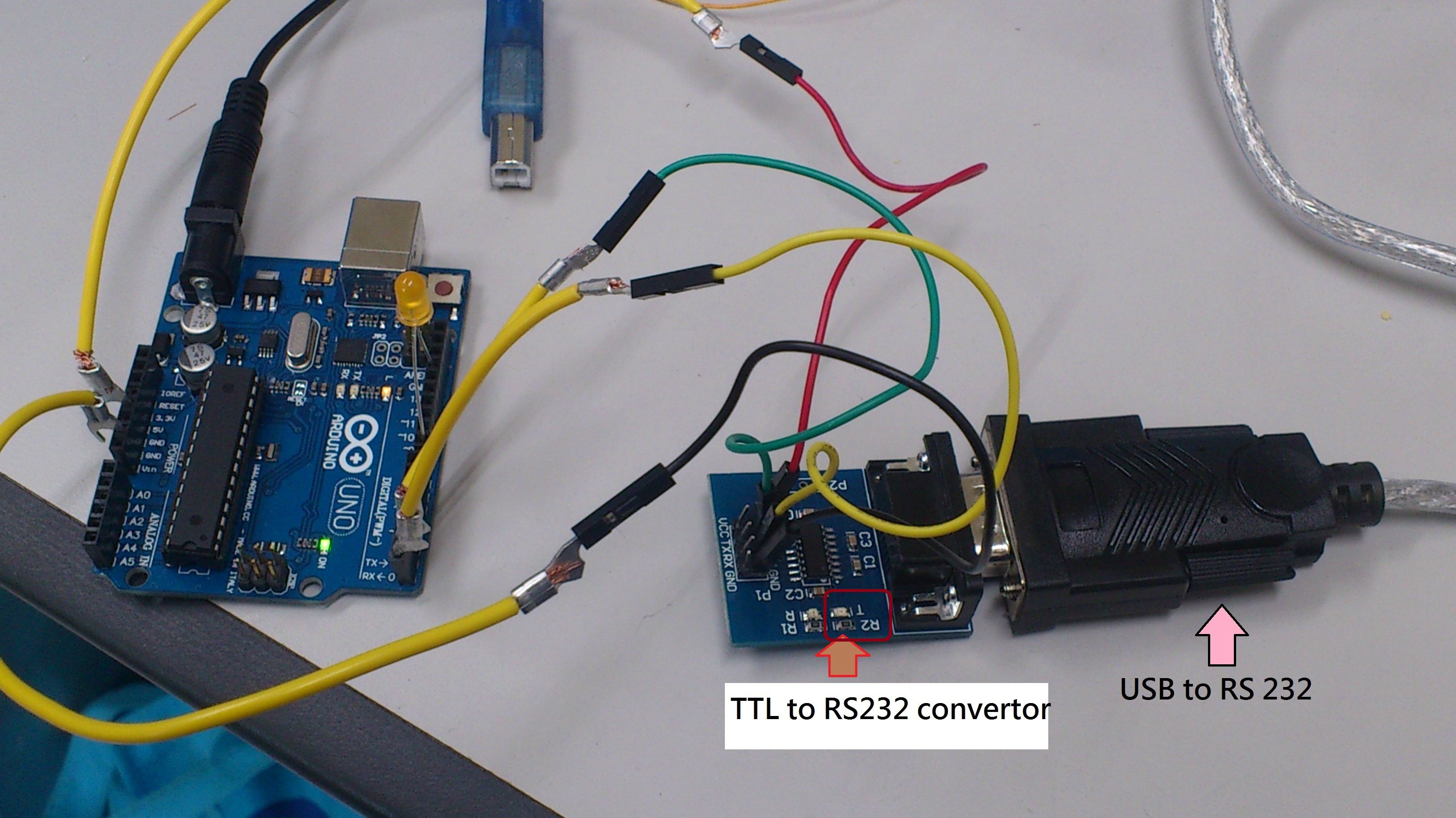
I read thru your code and saw provisions for RS-232, 485 and USB.
RS-232 and USB may behave the same way. There may be some USB driver start-up delay in the Leornado's, so I should look at its USB implementation for the Leornado's. Anyway it should be quite similar to RS-232. If you use USB-FTDI, then it is the same thing as RS-232.
RS-485 is a bit different, because it needs an additional pin to set the RS-485 transceiver to send mode. As long as a telegram is being sent, this pin must be kept active. This is internally written in the library when sending messages.
Again the communication mode is chosen when declaring the Modbus object.
How do I add this library and access the commands?
First an object must be declared. For instance,
Modbus com(1,0,0);
The constructor parameters are:
- u8id: node address 0=master, 1..247=slave
- u8serno: serial port used 0..3 (for Duemilia's and Uno's, it is always 0)
- u8txenpin pin for txen RS-485 (leave it at 0 for USB-FTDI or RS-232)
Beside the object constructor, it is important to declare an array with the data exchange area that would be used in the network. This would be the values that would be read or written.
In your setup(),
void setup() {
  com.begin(19200);
  com.setTimeOut( 2000 ); // <---- only for master, useless otherwise
  u32wait = millis() + 1000;
}
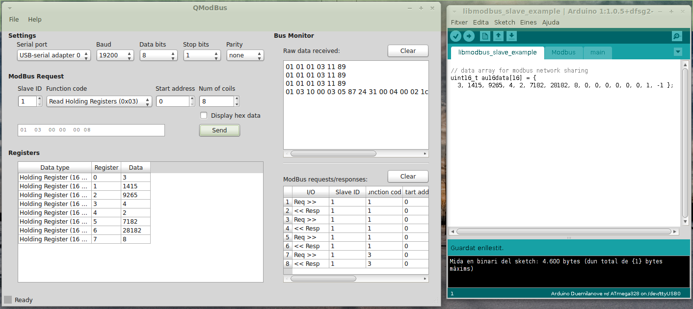
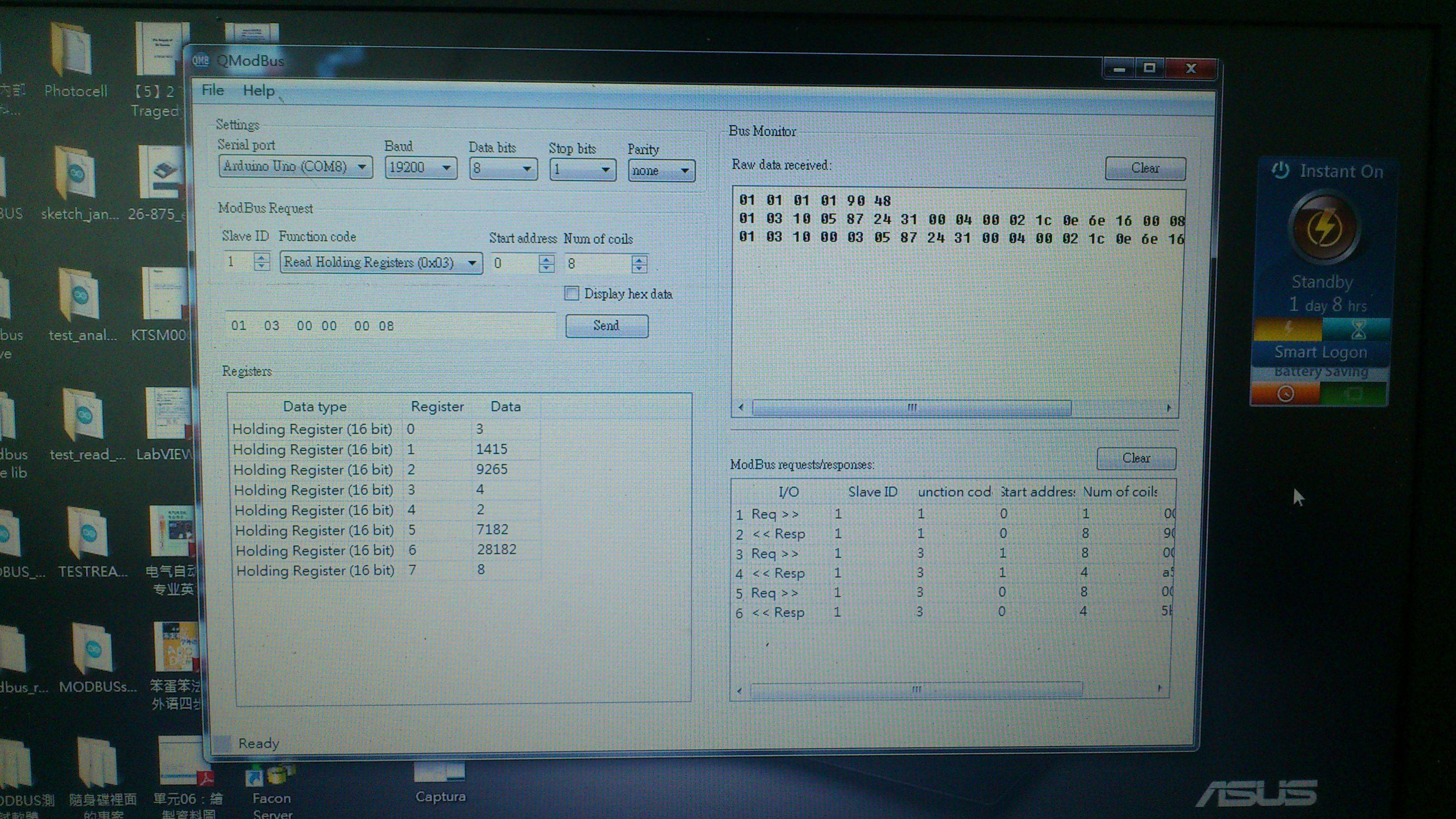
Here the driver needs to start its linked serial port as Serial.begin(19200). You can set any baudrate.
There may be an issue here regarding to the byte-frame implementation. Older Arduinos didn't allow other byte-frame formats other than 8N1 and I've seen that HardwareSerial library now allows others like 7E2 or 7E1.
Regarding to the loop(), here there are significant differences between the master and the slave:
Modbus Slave:
void loop() {
com.poll( dm, 10 );
}
This shall allow to refresh the dm array from the network. Beside this, our code can write a particular value according to an analog input (i.e. dm[3] = analogRead(0) ) or read its value and send it through a PWM output.
Modbus Master:
void loop() {
  switch( u8state ) {
  case 0:
    if (millis() > u32wait) u8state++;
    break;
  case 1:
    telegram.u8id = 1;
    telegram.u8fct = 3;
    telegram.u16RegAdd = 1;
    telegram.u16CoilsNo = 4;
    telegram.au16reg = dm;

    com.query( telegram );
    u8state++;
    break;
  case 2:
    com.poll();
    if (com.getState() == COM_IDLE) {
      u8state = 0;
      u32wait = millis() + 100;
    }
    break;
  }
}
Here there is another player: the telegram variable. The library defines a modbus_t structure, which is a Modbus master telegram. Most equipment manufacturers allow to define a Modbus Master query as here:
typedef struct {
  uint8_t u8id;  // slave number to access
  uint8_t u8fct; // Modbus function to implement
  uint16_t u16RegAdd; // slave register to access
  uint16_t u16CoilsNo; // coils or words to transfer
  uint16_t *au16reg; // pointer to the network exchange area inside master
}
modbus_t;
The idea is to make an small finite-state machine that shall query a message and then wait for an answer. If there is no answer, restart after a maximum time.
Most of the work is done, but there are some missing points. In the Master, the next functions are missing:
- FCT 1 & 2 are not working. A message is sent but there is no code to process it into the network exchange area;
- FCT 15 is not working. It doesn't generate a query message.
I'm looking forward your comments.
Best Regards,


