I am trying to use MPU 9265 to get the acceleration in x, y and z plane. However, I can't get it to work . I have used multiple 9250 libraries but none of them are working for me. I can 't even access the sensor. I keep getting weird symbols in the serial output. Can anyone give me an example code that works for mpu 9265?
Sensor Wiring:
Vcc = V
GND = GND
SDA = A4
SCL = A5
Hi @iqrakhan4987 ,
A usual reason for strange symbols is a wrong baudrate.
Did you check the baudrate
- in the sketch and
- in Serial Monitor?
ec2021
P.S.: If you still encounter problems you may have a look at this page
https://wolles-elektronikkiste.de/en/mpu9250-9-axis-sensor-module-part-1
- Install this library in the Arduino IDE:

- Copy one of the example sketches and upload to your device
This works for me with a MPU9265 device hooked up to a Arduino Nano .
Or you might also check this page
https://www.hackster.io/walid-abdelazeem/mpu9250-mpu9265-calibration-9-dof-c9da8e
1 Like
@ec2021
It works now. The baudrate was different in the sketch and the serial monitor.
However, I am not getting correct results. I keep getting the same results regardless if the IMU is moving or not.
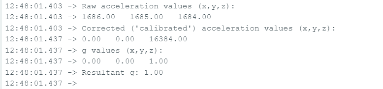
The following screenshot shows what I keep getting. Do you know why this is happening? I am using the library MPU9250_WE and the example MPU9250_acceleration_data.
For informed help, please read and follow the instructions in the "How to get the best out of this forum" post, linked at the head of every forum category.
Post the code, using code tags.
The code that I am using is :
/***************************************************************************
* Example sketch for the MPU9250_WE library
*
* This sketch shows how to obtain raw accleration data and g values from
* the MPU9250.
*
* For further information visit my blog:
*
* https://wolles-elektronikkiste.de/mpu9250-9-achsen-sensormodul-teil-1  (German)
* https://wolles-elektronikkiste.de/en/mpu9250-9-axis-sensor-module-part-1  (English)
*
***************************************************************************/

#include <MPU9250_WE.h>
#include <Wire.h>
#define MPU9250_ADDR 0x68

/* There are several ways to create your MPU9250 object:
 * MPU9250_WE myMPU9250 = MPU9250_WE()              -> uses Wire / I2C Address = 0x68
 * MPU9250_WE myMPU9250 = MPU9250_WE(MPU9250_ADDR)  -> uses Wire / MPU9250_ADDR
 * MPU9250_WE myMPU9250 = MPU9250_WE(&wire2)        -> uses the TwoWire object wire2 / MPU9250_ADDR
 * MPU9250_WE myMPU9250 = MPU9250_WE(&wire2, MPU9250_ADDR) -> all together
 * Successfully tested with two I2C busses on an ESP32
 */
MPU9250_WE myMPU9250 = MPU9250_WE(MPU9250_ADDR);

void setup() {
  Serial.begin(115200);
  Wire.begin();
  if(!myMPU9250.init()){
    Serial.println("MPU9250 does not respond");
  }
  else{
    Serial.println("MPU9250 is connected");
  }

  /* The slope of the curve of acceleration vs measured values fits quite well to the theoretical
   * values, e.g. 16384 units/g in the +/- 2g range. But the starting point, if you position the
   * MPU9250 flat, is not necessarily 0g/0g/1g for x/y/z. The autoOffset function measures offset
   * values. It assumes your MPU9250 is positioned flat with its x,y-plane. The more you deviate
   * from this, the less accurate will be your results.
   * The function also measures the offset of the gyroscope data. The gyroscope offset does not
   * depend on the positioning.
   * This function needs to be called at the beginning since it can overwrite your settings!
   */
  Serial.println("Position you MPU9250 flat and don't move it - calibrating...");
  delay(1000);
  myMPU9250.autoOffsets();
  Serial.println("Done!");

  /*  This is a more accurate method for calibration. You have to determine the minimum and maximum
   *  raw acceleration values of the axes determined in the range +/- 2 g.
   *  You call the function as follows: setAccOffsets(xMin,xMax,yMin,yMax,zMin,zMax);
   *  Use either autoOffset or setAccOffsets, not both.
   */
  //myMPU9250.setAccOffsets(-14240.0, 18220.0, -17280.0, 15590.0, -20930.0, 12080.0);

  /*  Sample rate divider divides the output rate of the gyroscope and accelerometer.
   *  Sample rate = Internal sample rate / (1 + divider)
   *  It can only be applied if the corresponding DLPF is enabled and 0<DLPF<7!
   *  Divider is a number 0...255
   */
  myMPU9250.setSampleRateDivider(5);

  /*  MPU9250_ACC_RANGE_2G      2 g
   *  MPU9250_ACC_RANGE_4G      4 g
   *  MPU9250_ACC_RANGE_8G      8 g
   *  MPU9250_ACC_RANGE_16G    16 g
   */
  myMPU9250.setAccRange(MPU9250_ACC_RANGE_2G);

  /*  Enable/disable the digital low pass filter for the accelerometer
   *  If disabled the bandwidth is 1.13 kHz, delay is 0.75 ms, output rate is 4 kHz
   */
  myMPU9250.enableAccDLPF(true);

  /*  Digital low pass filter (DLPF) for the accelerometer, if enabled
   *  MPU9250_DPLF_0, MPU9250_DPLF_2, ...... MPU9250_DPLF_7
   *   DLPF     Bandwidth [Hz]      Delay [ms]    Output rate [kHz]
   *     0           460               1.94           1
   *     1           184               5.80           1
   *     2            92               7.80           1
   *     3            41              11.80           1
   *     4            20              19.80           1
   *     5            10              35.70           1
   *     6             5              66.96           1
   *     7           460               1.94           1
   */
  myMPU9250.setAccDLPF(MPU9250_DLPF_6);

  /*  Set accelerometer output data rate in low power mode (cycle enabled)
   *   MPU9250_LP_ACC_ODR_0_24          0.24 Hz
   *   MPU9250_LP_ACC_ODR_0_49          0.49 Hz
   *   MPU9250_LP_ACC_ODR_0_98          0.98 Hz
   *   MPU9250_LP_ACC_ODR_1_95          1.95 Hz
   *   MPU9250_LP_ACC_ODR_3_91          3.91 Hz
   *   MPU9250_LP_ACC_ODR_7_81          7.81 Hz
   *   MPU9250_LP_ACC_ODR_15_63        15.63 Hz
   *   MPU9250_LP_ACC_ODR_31_25        31.25 Hz
   *   MPU9250_LP_ACC_ODR_62_5         62.5 Hz
   *   MPU9250_LP_ACC_ODR_125         125 Hz
   *   MPU9250_LP_ACC_ODR_250         250 Hz
   *   MPU9250_LP_ACC_ODR_500         500 Hz
   */
  //myMPU9250.setLowPowerAccDataRate(MPU9250_LP_ACC_ODR_500);

  /* sleep() sends the MPU9250 to sleep or wakes it up.
   * Please note that the gyroscope needs 35 milliseconds to wake up.
   */
  //myMPU9250.sleep(true);

 /* If cycle is set, and standby or sleep are not set, the module will cycle between
   *  sleep and taking a sample at a rate determined by setLowPowerAccDataRate().
   */
  //myMPU9250.enableCycle(true);

  /* You can enable or disable the axes for gyroscope and/or accelerometer measurements.
   * By default all axes are enabled. Parameters are:
   * MPU9250_ENABLE_XYZ  //all axes are enabled (default)
   * MPU9250_ENABLE_XY0  // X, Y enabled, Z disabled
   * MPU9250_ENABLE_X0Z
   * MPU9250_ENABLE_X00
   * MPU9250_ENABLE_0YZ
   * MPU9250_ENABLE_0Y0
   * MPU9250_ENABLE_00Z
   * MPU9250_ENABLE_000  // all axes disabled
   */
  //myMPU9250.enableAccAxes(MPU9250_ENABLE_XYZ);

}

void loop() {
  xyzFloat accRaw = myMPU9250.getAccRawValues();
  xyzFloat accCorrRaw = myMPU9250.getCorrectedAccRawValues();
  xyzFloat gValue = myMPU9250.getGValues();
  float resultantG = myMPU9250.getResultantG(gValue);

  Serial.println("Raw acceleration values (x,y,z):");
  Serial.print(accRaw.x);
  Serial.print("   ");
  Serial.print(accRaw.y);
  Serial.print("   ");
  Serial.println(accRaw.z);

  Serial.println("Corrected ('calibrated') acceleration values (x,y,z):");
  Serial.print(accCorrRaw.x);
  Serial.print("   ");
  Serial.print(accCorrRaw.y);
  Serial.print("   ");
  Serial.println(accCorrRaw.z);

  Serial.println("g values (x,y,z):");
  Serial.print(gValue.x);
  Serial.print("   ");
  Serial.print(gValue.y);
  Serial.print("   ");
  Serial.println(gValue.z);

  Serial.print("Resultant g: ");
  Serial.println(resultantG); // should always be 1 g if only gravity acts on the sensor.
  Serial.println();

  delay(1000);
}
If the raw acceleration values don't change as you move the sensor, there is either a problem with the sensor, the library or your use of it.
Try a different library, as it is impossible to guess which from the data you have posted.
You might also try this simple code to retrieve raw values from the MPU-6050, which is more or less compatible with the MPU-9250. Check for correct I2C address, though.
// MPU-6050 Short Example Sketch
// By Arduino User JohnChi
// August 17, 2014
// Public Domain
#include<Wire.h>
const int MPU_addr = 0x68; // I2C address of the MPU-6050
int16_t AcX, AcY, AcZ, Tmp, GyX, GyY, GyZ;

void setup() {
  Wire.begin();
  Wire.beginTransmission(MPU_addr);
  Wire.write(0x6B);  // PWR_MGMT_1 register
  Wire.write(0);     // set to zero (wakes up the MPU-6050)
  Wire.endTransmission(true);
  Serial.begin(9600);
}

void loop() {
  Wire.beginTransmission(MPU_addr);
  Wire.write(0x3B);  // starting with register 0x3B (ACCEL_XOUT_H)
  Wire.endTransmission(false);
  Wire.requestFrom(MPU_addr, 14); // request a total of 14 registers
  int16_t t = Wire.read();
  AcX = (t << 8) | Wire.read(); // 0x3B (ACCEL_XOUT_H) & 0x3C (ACCEL_XOUT_L)
  t = Wire.read();
  AcY = (t << 8) | Wire.read(); // 0x3D (ACCEL_YOUT_H) & 0x3E (ACCEL_YOUT_L)
  t = Wire.read();
  AcZ = (t << 8) | Wire.read(); // 0x3F (ACCEL_ZOUT_H) & 0x40 (ACCEL_ZOUT_L)
  t = Wire.read();
  Tmp = (t << 8) | Wire.read(); // 0x41 (TEMP_OUT_H) & 0x42 (TEMP_OUT_L)
  t = Wire.read();
  GyX = (t << 8) | Wire.read(); // 0x43 (GYRO_XOUT_H) & 0x44 (GYRO_XOUT_L)
  t = Wire.read();
  GyY = (t << 8) | Wire.read(); // 0x45 (GYRO_YOUT_H) & 0x46 (GYRO_YOUT_L)
  t = Wire.read();
  GyZ = (t << 8) | Wire.read(); // 0x47 (GYRO_ZOUT_H) & 0x48 (GYRO_ZOUT_L)
  t = Wire.read();
  Serial.print("AcX = "); Serial.print(AcX);
  Serial.print(" | AcY = "); Serial.print(AcY);
  Serial.print(" | AcZ = "); Serial.print(AcZ);
  Serial.print(" | Tmp = "); Serial.print(Tmp / 340.00 + 36.53); //equation for temperature in degrees C from datasheet
  Serial.print(" | GyX = "); Serial.print(GyX);
  Serial.print(" | GyY = "); Serial.print(GyY);
  Serial.print(" | GyZ = "); Serial.println(GyZ);
  delay(333);
}
I have two MPU 92/65 sensors and I tried to use both. I also used the following libraries:
MPU 9250: GitHub - hideakitai/MPU9250: Arduino library for MPU9250 Nine-Axis (Gyro + Accelerometer + Compass) MEMS MotionTracking™ Device
MPU9250_WE : GitHub - wollewald/MPU9250_WE: An Arduino library for the 9-axis accelerometer, gyroscope and magnetometer MPU9250 and MPU6500. It contains many example sketches make it easy to use.
MPU9250_asukiaaa: GitHub - asukiaaa/MPU9250_asukiaaa: A library for arduino to read value of MPU9250.
GitHub - bolderflight/invensense-imu: Arduino and CMake library for communicating with the InvenSense MPU-6500, MPU-9250 and MPU-9255 nine-axis IMUs.
I have tried multiple examples, but the data I am recieving is not correct.
@jremington I tried using the above code you provided with the correct I2C address of the sensor but I am getting the following output:

The sensor is not responding, so either it is not working, or I2C is not working.
Run the I2C address scanner program to check communications. Check for the required pullup resistors.
If you are using a 5V Arduino, logic level shifters are required to communicate with a 3.3V sensor.
All of the MPU series of sensors are obsolete and manufacture has been discontinued, so consider using a more modern IMU.
I uploaded the sketch from post #5 to my Arduino Nano with an MPU9265 breakout board wired by I2C and got changing output while moving the MPU.
This is a modified version of this sketch
/***************************************************************************
* Example sketch for the MPU9250_WE library
*
* This sketch shows how to obtain raw accleration data and g values from
* the MPU9250.
*
* For further information visit my blog:
*
* https://wolles-elektronikkiste.de/mpu9250-9-achsen-sensormodul-teil-1  (German)
* https://wolles-elektronikkiste.de/en/mpu9250-9-axis-sensor-module-part-1  (English)
*

 Modified 2024/03/07 by ec2021

 if
 #define PRINTTABLE

 Only prints a table header once and
 the measurement data per row (in the same order as the table header)

 if
 //#define PRINTTABLE

 Prints the data as in the original sketch

***************************************************************************/

#include <MPU9250_WE.h>
#include <Wire.h>
#define MPU9250_ADDR 0x68

#define PRINTTABLE


/* There are several ways to create your MPU9250 object:
 * MPU9250_WE myMPU9250 = MPU9250_WE()              -> uses Wire / I2C Address = 0x68
 * MPU9250_WE myMPU9250 = MPU9250_WE(MPU9250_ADDR)  -> uses Wire / MPU9250_ADDR
 * MPU9250_WE myMPU9250 = MPU9250_WE(&wire2)        -> uses the TwoWire object wire2 / MPU9250_ADDR
 * MPU9250_WE myMPU9250 = MPU9250_WE(&wire2, MPU9250_ADDR) -> all together
 * Successfully tested with two I2C busses on an ESP32
 */
MPU9250_WE myMPU9250 = MPU9250_WE(MPU9250_ADDR);

void setup() {
  Serial.begin(115200);
  Wire.begin();
  if(!myMPU9250.init()){
#ifndef PRINTTABLE
    Serial.println("MPU9250 does not respond");
#endif
  }
  else{
#ifndef PRINTTABLE
    Serial.println("MPU9250 is connected");
#endif
  }

  /* The slope of the curve of acceleration vs measured values fits quite well to the theoretical
   * values, e.g. 16384 units/g in the +/- 2g range. But the starting point, if you position the
   * MPU9250 flat, is not necessarily 0g/0g/1g for x/y/z. The autoOffset function measures offset
   * values. It assumes your MPU9250 is positioned flat with its x,y-plane. The more you deviate
   * from this, the less accurate will be your results.
   * The function also measures the offset of the gyroscope data. The gyroscope offset does not
   * depend on the positioning.
   * This function needs to be called at the beginning since it can overwrite your settings!
   */
#ifndef PRINTTABLE
  Serial.println("Position you MPU9250 flat and don't move it - calibrating...");
#endif
  delay(1000);
  myMPU9250.autoOffsets();
#ifndef PRINTTABLE
  Serial.println("Done!");
#endif

  /*  This is a more accurate method for calibration. You have to determine the minimum and maximum
   *  raw acceleration values of the axes determined in the range +/- 2 g.
   *  You call the function as follows: setAccOffsets(xMin,xMax,yMin,yMax,zMin,zMax);
   *  Use either autoOffset or setAccOffsets, not both.
   */
  //myMPU9250.setAccOffsets(-14240.0, 18220.0, -17280.0, 15590.0, -20930.0, 12080.0);

  /*  Sample rate divider divides the output rate of the gyroscope and accelerometer.
   *  Sample rate = Internal sample rate / (1 + divider)
   *  It can only be applied if the corresponding DLPF is enabled and 0<DLPF<7!
   *  Divider is a number 0...255
   */
  myMPU9250.setSampleRateDivider(5);

  /*  MPU9250_ACC_RANGE_2G      2 g
   *  MPU9250_ACC_RANGE_4G      4 g
   *  MPU9250_ACC_RANGE_8G      8 g
   *  MPU9250_ACC_RANGE_16G    16 g
   */
  myMPU9250.setAccRange(MPU9250_ACC_RANGE_2G);

  /*  Enable/disable the digital low pass filter for the accelerometer
   *  If disabled the bandwidth is 1.13 kHz, delay is 0.75 ms, output rate is 4 kHz
   */
  myMPU9250.enableAccDLPF(true);

  /*  Digital low pass filter (DLPF) for the accelerometer, if enabled
   *  MPU9250_DPLF_0, MPU9250_DPLF_2, ...... MPU9250_DPLF_7
   *   DLPF     Bandwidth [Hz]      Delay [ms]    Output rate [kHz]
   *     0           460               1.94           1
   *     1           184               5.80           1
   *     2            92               7.80           1
   *     3            41              11.80           1
   *     4            20              19.80           1
   *     5            10              35.70           1
   *     6             5              66.96           1
   *     7           460               1.94           1
   */
  myMPU9250.setAccDLPF(MPU9250_DLPF_6);

  /*  Set accelerometer output data rate in low power mode (cycle enabled)
   *   MPU9250_LP_ACC_ODR_0_24          0.24 Hz
   *   MPU9250_LP_ACC_ODR_0_49          0.49 Hz
   *   MPU9250_LP_ACC_ODR_0_98          0.98 Hz
   *   MPU9250_LP_ACC_ODR_1_95          1.95 Hz
   *   MPU9250_LP_ACC_ODR_3_91          3.91 Hz
   *   MPU9250_LP_ACC_ODR_7_81          7.81 Hz
   *   MPU9250_LP_ACC_ODR_15_63        15.63 Hz
   *   MPU9250_LP_ACC_ODR_31_25        31.25 Hz
   *   MPU9250_LP_ACC_ODR_62_5         62.5 Hz
   *   MPU9250_LP_ACC_ODR_125         125 Hz
   *   MPU9250_LP_ACC_ODR_250         250 Hz
   *   MPU9250_LP_ACC_ODR_500         500 Hz
   */
  //myMPU9250.setLowPowerAccDataRate(MPU9250_LP_ACC_ODR_500);

  /* sleep() sends the MPU9250 to sleep or wakes it up.
   * Please note that the gyroscope needs 35 milliseconds to wake up.
   */
  //myMPU9250.sleep(true);

 /* If cycle is set, and standby or sleep are not set, the module will cycle between
   *  sleep and taking a sample at a rate determined by setLowPowerAccDataRate().
   */
  //myMPU9250.enableCycle(true);

  /* You can enable or disable the axes for gyroscope and/or accelerometer measurements.
   * By default all axes are enabled. Parameters are:
   * MPU9250_ENABLE_XYZ  //all axes are enabled (default)
   * MPU9250_ENABLE_XY0  // X, Y enabled, Z disabled
   * MPU9250_ENABLE_X0Z
   * MPU9250_ENABLE_X00
   * MPU9250_ENABLE_0YZ
   * MPU9250_ENABLE_0Y0
   * MPU9250_ENABLE_00Z
   * MPU9250_ENABLE_000  // all axes disabled
   */
  //myMPU9250.enableAccAxes(MPU9250_ENABLE_XYZ);
 #ifdef PRINTTABLE
   printTableHeader();
 #endif
}

xyzFloat accRaw;
xyzFloat accCorrRaw;
xyzFloat gValue;
float resultantG;

void loop() {
  accRaw = myMPU9250.getAccRawValues();
  accCorrRaw = myMPU9250.getCorrectedAccRawValues();
  gValue = myMPU9250.getGValues();
  resultantG = myMPU9250.getResultantG(gValue);
#ifdef PRINTTABLE
  printTable();
#else
  printOriginal();
#endif
}

void printTableHeader(){
// millis()
//  Serial.println("Raw acceleration values (x,y,z):");
//  Serial.println("Corrected ('calibrated') acceleration values (x,y,z):");
//  Serial.println("g values (x,y,z):");
//  Serial.print("Resultant g: ");
Serial.println("millis(),accRaw.x,accRaw.y,accRaw.z,accCorrRaw.x,accCorrRaw.y,accCorrRaw.z,gValue.x,gValue.y,gValue.z,resultantG");

}

void printTable(){
  Serial.print(millis());
  Serial.print(",");
//  Serial.println("Raw acceleration values (x,y,z):");
  Serial.print(accRaw.x);
  Serial.print(",");
  Serial.print(accRaw.y);
  Serial.print(",");
  Serial.print(accRaw.z);
  Serial.print(",");
//  Serial.println("Corrected ('calibrated') acceleration values (x,y,z):");
  Serial.print(accCorrRaw.x);
  Serial.print(",");
  Serial.print(accCorrRaw.y);
  Serial.print(",");
  Serial.print(accCorrRaw.z);
  Serial.print(",");
//  Serial.println("g values (x,y,z):");
  Serial.print(gValue.x);
  Serial.print(",");
  Serial.print(gValue.y);
  Serial.print(",");
  Serial.print(gValue.z);
  Serial.print(",");
//  Serial.print("Resultant g: ");
  Serial.println(resultantG); // should always be 1 g if only gravity acts on the sensor.
  delay(1000);
}

void printOriginal(){
  Serial.println("Raw acceleration values (x,y,z):");
  Serial.print(accRaw.x);
  Serial.print("   ");
  Serial.print(accRaw.y);
  Serial.print("   ");
  Serial.println(accRaw.z);

  Serial.println("Corrected ('calibrated') acceleration values (x,y,z):");
  Serial.print(accCorrRaw.x);
  Serial.print("   ");
  Serial.print(accCorrRaw.y);
  Serial.print("   ");
  Serial.println(accCorrRaw.z);

  Serial.println("g values (x,y,z):");
  Serial.print(gValue.x);
  Serial.print("   ");
  Serial.print(gValue.y);
  Serial.print("   ");
  Serial.println(gValue.z);

  Serial.print("Resultant g: ");
  Serial.println(resultantG); // should always be 1 g if only gravity acts on the sensor.
  Serial.println();

  delay(1000);

}
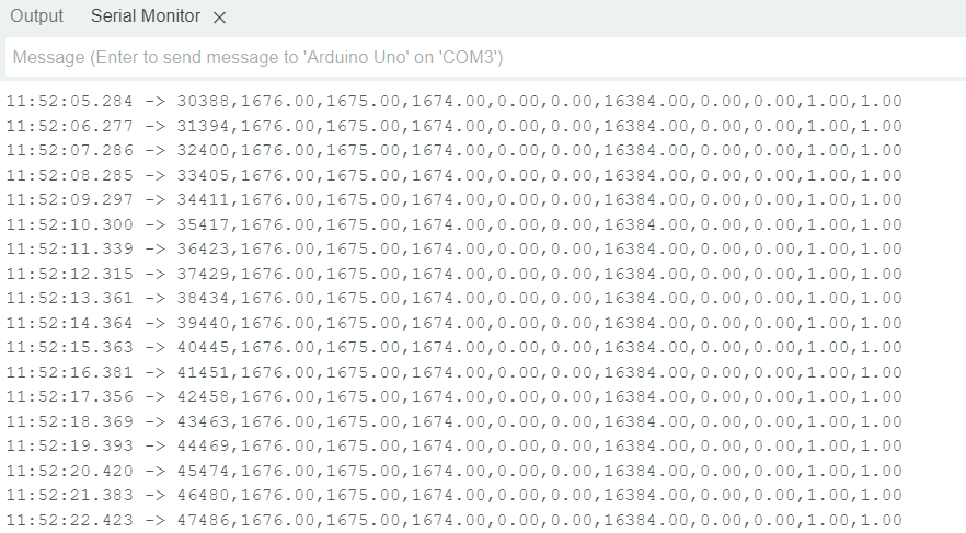
that prints all data per measurement in one line so that they can easily be collected in a table and/or can be visualized in the Serial Plotter:

This is a table I got from this sketch (first row = time in millis()):

I suggest to use this sketch and the Serial Plotter from the IDE to see if there are any changes when moving the MPU.
If it does not work there might be an issue with your wiring...
BTW: Did you mention which Arduino board you use?
P.S.: Sorry, the #define PRINTTABLE in the sketch was commented out; just changed it so that it works as described ...
Even with this new sketch, the acceleration values are not changing despite moving the sensor.
I am using an Arduino Uno board. My wiring looks fine to me. (VCC -5V , GND -GND , SDA - A4 , SCL -A5). I am starting to think that its an issue with the sensor.
This topic was automatically closed 180 days after the last reply. New replies are no longer allowed.