Hi there!
This is my first post.
I'm building a dyno for mopeds/motorbikes and are going to use an arduino uno together with Simple Dyno software.
I need a way to pick up engine rpm and found this circuit:
My problem is the pins of the ne555 in the circuit I found is not named correctly.
Pin 2(trigger) - IN-?
Pin 4(reset) - not connected?
Pin 5(control voltage) - not connected?
Pin 6(threshold) - IN+?
If there's anything else with the circuit worth commenting on, please feel free to do so.
I've just started learning electronics and hope to in time be able to figure out stuff like this myself but at the moment I'm really eager to get this dyno up and running!
Hi,
You can consider noise as unwanted AC, in the environment you will be in, you will have electrical interference induced onto the power supply wires.
The capacitor begins to conduct electricity as the frequency of a voltage across it increases, DC current does not flow but AC does. The cap shorts the noise out so it does not pass to the LM555.
The cap on pin 5 is there because the LM555 uses a potential divider inside it to work with the comparator, part of the divider is connected to pin 5.
This divider is also sensitive to noise.
The best place for the capacitive pickup is near the plug end of the lead, not the distributor/coil as this is where all the firing signals originate.
So, I built the circuit but I'm not getting it to work.
I had wired the bt149 backwards, and thought that was the problem, but guess not.
Questions:
Can the backwards wired thyristor have caused any damage to itself or the 555?
My pickup wire is about 4m long shielded microphone cable - too long?
I tried with and without the shield connected to arduino ground, no difference.
I tried both twisting the wire(shield and outer insulation stripped off)around the ignition lead and using a metal clamp.
I've gone trough the circuit multiple times to check for errors, can't find anything wrong.
Thanks for the reply!
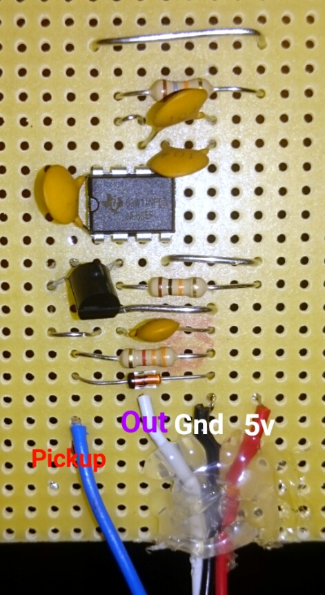
There is a jumper from pin 1 to ground, I bent the bt149 to show where it's pins are connected, the end of the jumper is hiding under it.
Yep, got a multimeter.
You are right, I'll order some sockets!
Hi,
Have you got the gnd of the circuit connected to the gnd of the arduino?
Also if you jumper the gate of the SCR to the 5V positive, it should trigger the SCR.
Use your DMM to see if pin2 of LM555 goes to gnd when you connect gate to 5V.