Good afternoon everyone.
I am developing a line follower robot with a PID algorythm. I stopped working on the robot in early December, and resumed the project last week. The code I used made the robot complete a circle, however, it was quite slow. Furthermore, when I was testing it out today, I couldn't get it to do the makeshift course I made at home, and the actual course from the robtics club. It would either only turn on one wheel, or not move entirely. The code I used was adapted from a website whoose name I cannot recall, but I'm thankfull for the people over there for the help, as it is hard to do these things with my age.
The code is the following:
// Motor and sensor pins
#define engineR 11
#define inputR1 8
#define inputR2 9
#define engineL 13
#define inputL1 12
#define inputL2 10
// Sensor pins
#define sensorRR A0
#define sensorR A1
#define sensorRM A2
#define sensorLM A3
#define sensorL A4
#define sensorLL A5
QTRSensors qtr;
const int sensorCount = 6;
const int sensorPins[] = {A0, A1, A2, A3, A4, A5};
uint16_t sensorValues[sensorCount];
int P, D, I, previousError, PIDvalue, error;
int lsp, rsp, x;
int lfspeed = 400;
float Kp = 1.6; // Adjust this value based on experimentation
float Kd = 0.1; // Adjust this value based on experimentation
float Ki = 0.01; // Adjust this value based on experimentation
void setup() {
// Sensor setup
qtr.setTypeAnalog();
qtr.setSensorPins((const uint8_t[]){sensorRR, sensorR, sensorRM, sensorLM, sensorL, sensorLL}, sensorCount);
qtr.setEmitterPin(2);
// Calibration
delay(500);
for (uint16_t i = 0; i < 400; i++) {
qtr.calibrate();
}
// Motor and input pin setup
pinMode(engineR, OUTPUT);
pinMode(inputR1, OUTPUT);
pinMode(inputR2, OUTPUT);
pinMode(engineL, OUTPUT);
pinMode(inputL1, OUTPUT);
pinMode(inputL2, OUTPUT);
Serial.begin(9600);
}
void loop() {
linefollow();
}
void linefollow() {
int error = analogRead(sensorL) - analogRead(sensorR);
P = error;
I = I + error;
D = error - previousError;
PIDvalue = (Kp * P) + (Ki * I) + (Kd * D);
previousError = error;
lsp = lfspeed - PIDvalue;
rsp = lfspeed + PIDvalue;
if (lsp > 255) {
lsp = 255;
}
if (lsp < 0) {
lsp = 0;
}
if (rsp > 255) {
rsp = 255;
}
if (rsp < 0) {
rsp = 0;
}
Serial.println(rsp);
Serial.println(lsp);
digitalWrite(inputL1, HIGH);
digitalWrite(inputL2, LOW);
digitalWrite(inputR1, HIGH);
digitalWrite(inputR2, LOW);
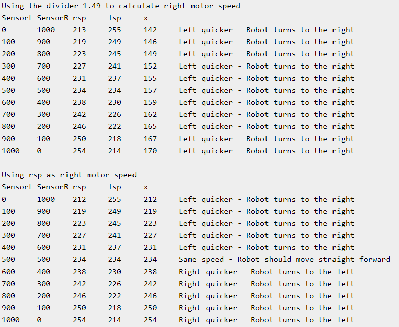
x = rsp/1,49;
analogWrite(engineR, x);
analogWrite(engineL, lsp);
}
I used an Arduino Mega, an L298n motor driver, a QTR8 sensor arry and two I belive 9 V batteries. The QTR Sensors library will be necessary.
I pray that the good samaritans of this forum can help help me, and I wish the best for their families.
Salutations, Robert