Help with video game controller using rotary encoder on the Arduino Leonardo

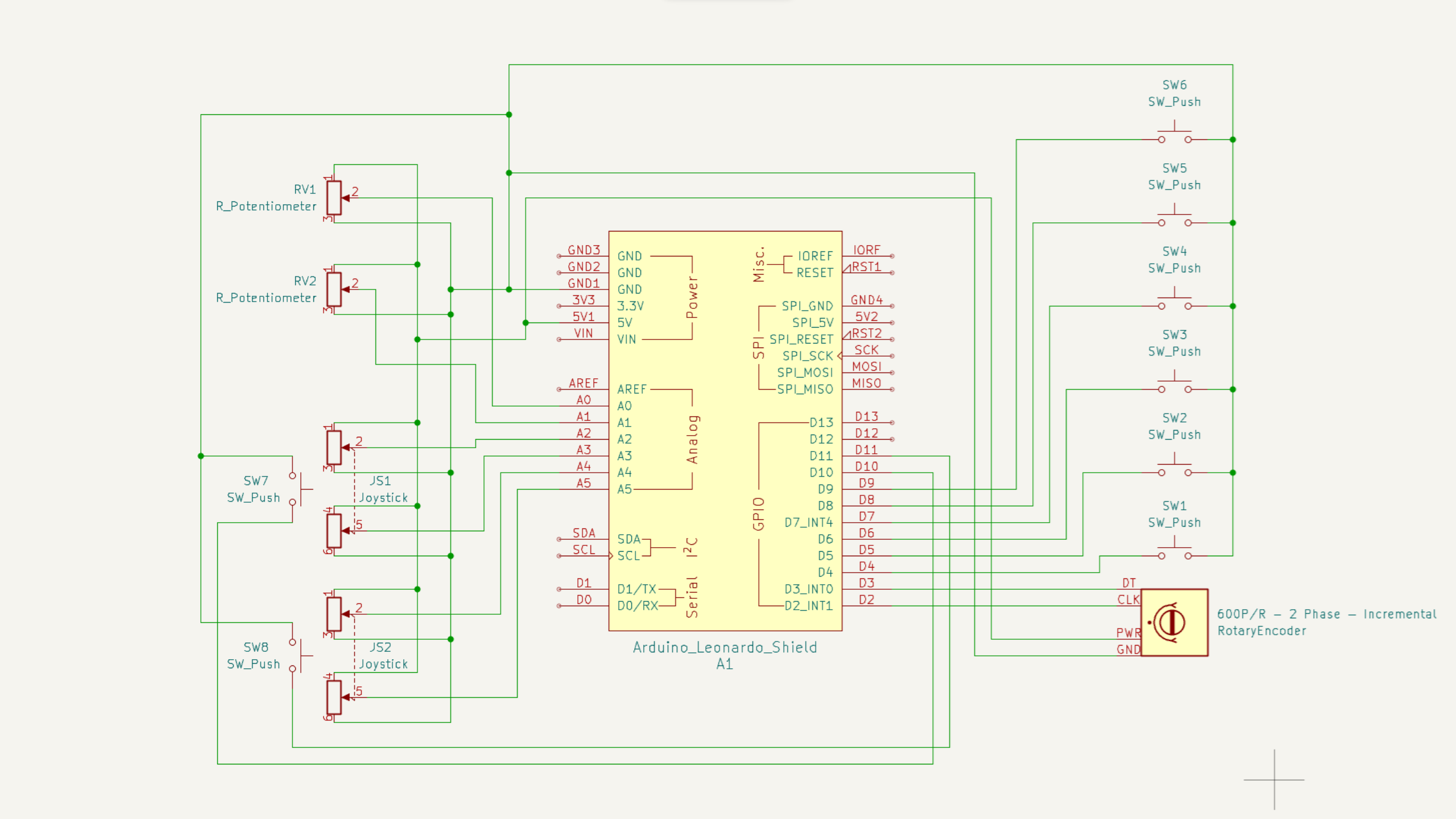
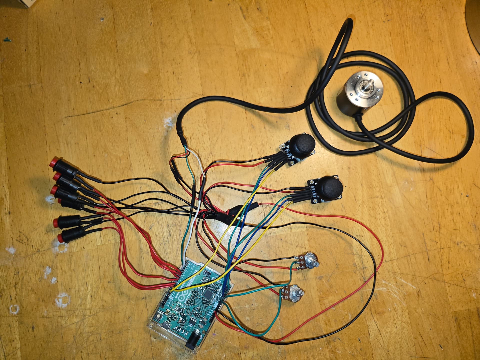
I've been working on a project to make a video game steering wheel for PC, using a rotary encoder. I know very little about programming, in general. I have all of the hardware wired up correctly, and the code is mostly complete. I'm using an XInput library to control the six buttons, two joysticks with push switch, two potentiometers and the rotary encoder. Everything works as intended, except for the rotary encoder. The serial monitor displays very accurate values, so I know that it's reading correctly. I just can't figure out, after a whole week of tinkering and problem-solving, how to get it to interface with any game or mapping software that I've tried to use. I just want to control my games with this DIY controller. The microcontroller that I am using is the Arduino Leonardo. Can anyone help me figure this out? Any help is appreciated.

Here is my current code:

#include <XInput.h>

#include <Rotary.h>


Rotary rotary = Rotary(2, 3);


int counter = 0;


void setup() {

  {


    Serial.begin(57600);


    attachInterrupt(0, rotate, CHANGE);

    attachInterrupt(1, rotate, CHANGE);

  }


  XInput.setAutoSend(false);

  XInput.setJoystickRange(0, 1023);

  XInput.begin();


  pinMode(2, INPUT_PULLUP);

  pinMode(3, INPUT_PULLUP);

  pinMode(4, INPUT_PULLUP);

  pinMode(5, INPUT_PULLUP);

  pinMode(6, INPUT_PULLUP);

  pinMode(7, INPUT_PULLUP);

  pinMode(12, INPUT_PULLUP);

  pinMode(13, INPUT_PULLUP);  

}


void loop() {


  XInput.setTrigger(TRIGGER_LEFT, analogRead(A0));

  XInput.setTrigger(TRIGGER_RIGHT, analogRead(A1));


  XInput.setJoystick(JOY_LEFT, analogRead(A2), analogRead(A3));

  XInput.setJoystick(JOY_RIGHT, analogRead(A4), analogRead(A5));


  XInput.setButton(BUTTON_A, !digitalRead(10));

  XInput.setButton(BUTTON_B, !digitalRead(11));

  XInput.setButton(BUTTON_X, !digitalRead(4));

  XInput.setButton(BUTTON_Y, !digitalRead(5));

  XInput.setButton(BUTTON_LB, !digitalRead(6));

  XInput.setButton(BUTTON_RB, !digitalRead(7));

  XInput.setButton(BUTTON_L3, !digitalRead(12));

  XInput.setButton(BUTTON_R3, !digitalRead(13));


  XInput.send();

}


void rotate() {

  unsigned char result = rotary.process();

  if (result == DIR_CW) {

    counter++;

    Serial.println(counter);

  } else if (result == DIR_CCW) {

    counter--;

    Serial.println(counter);

  }

}

There is not nearly enough information to even guess what the problem is.

For help, clearly explain what the controller does now, what you want it to do instead, describe what you changed, the result of making those changes and why that failed to work.

Posting error messages and a wiring diagram would be helpful.

Post links to documents explaining what the games expect from your controller.

Posting instructions can be found in the "How to get the best out of this forum post".

1 Like

Thank you for the reply. I will collect the necessary information and post it soon. I should have read "How to get the best out of this forum". I guess I'm just being impatient.

Posting an annotated schematic showing all connections, power, ground, power sources and links to technical information on hardware devices will be a big help for us helping you.

1 Like

What is this library? There are many libraries for this sort of thing, sadly not all of them implement the correct algorithm.

One that does employ the correct algorithm is this one:-
Rotary Encoder

I have used it many times.

1 Like

would second recommendation by @Grumpy_Mike
running code based on library File>Examples>Encoder>Basic

// Leonardo - File>Examples>Encoder>Basic

/* Encoder Library - Basic Example
 * http://www.pjrc.com/teensy/td_libs_Encoder.html
 *
 * This example code is in the public domain.
 */

#include <Encoder.h>

// Change these two numbers to the pins connected to your encoder.
//   Best Performance: both pins have interrupt capability
//   Good Performance: only the first pin has interrupt capability
//   Low Performance:  neither pin has interrupt capability
//Encoder myEnc(4, 5);   // arduino uno pins 2 and 2
Encoder myEnc(2, 3);   // Leonardo pins 2 and 3
//   avoid using pins with LEDs attached
int switchPin=5;       // switch is pin 5

void setup() {
  Serial.begin(115200);
  Serial.println("Basic Encoder Test:");
    pinMode(switchPin, INPUT_PULLUP);
}

long oldPosition  = -999;

void loop() {
  static int sw=0, offset=0;
  // display switch on press and reset position to 0
  if(!digitalRead(switchPin) != sw) 
  {
    sw=!digitalRead(switchPin);
    if(!digitalRead(switchPin))Serial.println("switch");
    offset=oldPosition;
  }
  long newPosition = myEnc.read();
  if (newPosition != oldPosition) {
    oldPosition = newPosition;
    Serial.println(newPosition-offset);
  }
}

on a Leonardo gives results

1
2
3
4
5
6
7
8
7
8
7
6
5
4
3
2
1
0
-1
-2
-3
-4
-3
-4
-5
-6
-7
-8

photo running on a The Things UNO which is based on the Leonardo

2 Likes

As far as I know, the XInput library don't support rotary encoder. It was written to emulate an Xbox 360 controller (witch don't have a rotary encoder). It is able to capture switches and potentiometers or linear hall-sensors.
What exact device on your steering wheel project is using a rotary encoder? Are you able to replace the encoder with a potentiometer or linear hall sensor?
Please show some pictures.

1 Like

While a real steering wheel will not have continuous 360˚ rotation then nether will a pot, unless you use one of the very expensive 360˚ pots.

I am not sure that a linear hall sensor would work, but a rotary hall sensor would give you 360˚ rotation.

See:- Rotary Hall Sensor

1 Like

Hello again! Thank you everyone for the help. I apologize for the late reply. I took a break from this project for a few days. I have some more information that I hope will help. I drew a very crude schematic of my setup using Kicad. It's not pretty, but I hope it's enough for you to see what I've done. The "Arduino_Leonardo_Shield" symbol depicted in the schematic has a different pin layout than the actual board, but the pin labels are the same. I could not find a symbol for an analog stick with center click on Kicad, so I added 2 dual potentiometers with 2 push buttons to the left of the symbols labeled "Joystick". I also had to edit the rotary encoder symbol to better reflect the rotary encoder that I have purchased for this setup. The reason I connected the rotary encoder's CLK and DT to pin 2 and 3, is because they support interrupts. I read somewhere that this is important, but I can't remember why. I also had to update the code because I have changed a few pin connections since my first post.

As @robby77 mentioned, I don't think that XInput supports the use of rotary encoders. This is probably due to XInput only having a set amount of controls (buttons, Potentiometers, etc.). It's only emulating the controls that an Xbox controller has. I may have to look into using DirectInput instead. That would allow me to use more controls for my games, including a rotary encoder for the steering wheel.

My goal is to play driving simulator games using this DIY controller. I will do some more research on implementing DirectInput. Let me know if there is any other information that could help.

Here is the updated code:

#include <XInput.h>
#include <Rotary.h>

Rotary rotary = Rotary(2, 3);

int counter = 0;

void setup() {
  {

    Serial.begin(57600);

    attachInterrupt(0, rotate, CHANGE);
    attachInterrupt(1, rotate, CHANGE);
  }

  XInput.setAutoSend(false);
  XInput.setJoystickRange(0, 1023);
  XInput.begin();

  pinMode(2, INPUT_PULLUP);
  pinMode(3, INPUT_PULLUP);
  pinMode(4, INPUT_PULLUP);
  pinMode(5, INPUT_PULLUP);
  pinMode(6, INPUT_PULLUP);
  pinMode(7, INPUT_PULLUP);
  pinMode(8, INPUT_PULLUP);
  pinMode(9, INPUT_PULLUP);
  pinMode(10, INPUT_PULLUP);
  pinMode(11, INPUT_PULLUP);
}

void loop() {


  XInput.setTrigger(TRIGGER_LEFT, analogRead(A0));
  XInput.setTrigger(TRIGGER_RIGHT, analogRead(A1));

  XInput.setJoystick(JOY_LEFT, analogRead(A2), analogRead(A3));
  XInput.setJoystick(JOY_RIGHT, analogRead(A4), analogRead(A5));

  XInput.setButton(BUTTON_A, !digitalRead(4));
  XInput.setButton(BUTTON_B, !digitalRead(5));
  XInput.setButton(BUTTON_X, !digitalRead(6));
  XInput.setButton(BUTTON_Y, !digitalRead(7));
  XInput.setButton(BUTTON_LB, !digitalRead(8));
  XInput.setButton(BUTTON_RB, !digitalRead(9));
  XInput.setButton(BUTTON_L3, !digitalRead(10));
  XInput.setButton(BUTTON_R3, !digitalRead(11));

  XInput.send();
}

void rotate() {
  unsigned char result = rotary.process();
  if (result == DIR_CW) {
    counter++;
    Serial.println(counter);
  } else if (result == DIR_CCW) {
    counter--;
    Serial.println(counter);
  }
}

The schematic:

A picture of my terrible wire management:

I am using this rotary encoder library: arduino/libraries/Rotary at master · buxtronix/arduino · GitHub

Current state: All of the buttons, potentiometers and joysticks are working perfectly in Euro Truck Simulator, except for the rotary encoder, which I want to use as a steering axis. The reason why I selected a rotary encoder for this purpose, is to get 900º or more of steering range. I would like to be able to dynamically adjust the steering range for games that need more precision, like Euro Truck Simulator or BeamNG.drive. I also need to find a solution to lock the steering wheel at a certain point so it doesn't continue to rotate when I'm at the steering lock (ie. 900º).

Desired state: I want to use the rotary encoder as an axis to steer the car or truck in some of my games. I have a decent Logitech steering wheel, pedals and shifter, but I want a custom and portable setup to bring to friends houses.

I'm not sure how to explain what I've changed, the results of the changes and why they failed. I don't think I even know, myself if I'm being honest.

I've worked through the errors in the code, but I am still unable to find a solution to add the rotary encoder as an axis in XInput. I will try to use DirectInput or some other type of HID.

I am also unsure of what the games expect from my contoller. I just know that I want to play driving simulator games with this device.

Thank you for taking time out of your day to help. I appreciate all that people do on this forum.

The Serial Monitor shows very precise values for the rotary encoder, so I assume that it's working correctly. The values don't skip or judder. I assume that if it's not set up right, it will give incorrect readings.

From the comments above about the Xinput library not supporting the rotary encoder, it appears that you currently do not have enough information on how to proceed. I suggest to post on gaming forums for advice, as the Arduino forum has a different focus.

It might be possible make the rotary coder "look like" some input that the library supports, but again, you will need detailed information about the expected data protocols.

1 Like

Thank you for the reply. I have very little knowledge about making electronics and coding. I need to do more research on the subject. I saw a video on Youtube about someone who made something like this and thought, "I can make that". I think I was too impulsive and hastefully bought the supplies I thought I would need for this project, not thinking how much I needed to learn to complete it. I have no more questions for now. I'm just going to do some more searching. The fun part of this project for me is the process of making it, not just using the finished product. I will post later if I have any more questions. Thank you again. I appreciate your help.

 if (result == DIR_CW) {
    counter++;
    Serial.println(counter);
  } else if (result == DIR_CCW) {
    counter--;
    Serial.println(counter

Don't use Serial.print within an ISR. Set a flag to be acted upon in the main code.

1 Like

Thank you for the info. I will make the necessary modifications when I get home.

So is that a physical lock, as in the wheel will not turn any more? Or is it a virtual lock when the wheel still spins but does not exceed a specific value?

If the latter, this is easy to do, you simply use a while loop, that checks if the value of the counter exceeds your limiting number, and if it does then decrement the counter.

A physical lock would involve the same sort of logic but you would have to have a solenoid that clamps the wheel until the count is less than the maximum value.

I am not sure, but from your photograph that rotary encoder looks like a hall effect one which if true explains why you do not need two 0.1uF ceramic capacitors between output pulses and ground.

1 Like