High impedance solution for analog read ?

hello all,

i got wrong reading when read voltage to analog input with high impadance resistor divider, i'm using a million ohm resistor for make it 5v to analog input, it's because of my reading is dc high voltage, it's about 120Vdc.

i read at this forums, arduino analog input is only recomended for <10K Ohm resistor divider impedance, if bigger than that then its cause wrong reading...

what i read at this forum, the solution for high impedance is using buffer with an Op Amp in a voltage follower configuration. and i found in google, the suitable Op Amp type for voltage follower configuration to arduino is MCP6041 / 2 / 4.

my question is, if i can not find that Op Amp (MCP6041), any sugestion of other Op Amp, maybe the equivalent one?
i mean, the common Op Amp (easy find in market), like LM358 or etc but it can suitable for my case above.

sorry for my bad english, because it's not my native language.

thanks.

The common solution is to add a 100n capacitor between analogue pin and ground.
Leo..

Wawa:
The common solution is to add a 100n capacitor between analogue pin and ground.
Leo..

ok, i will try it, what if adding the 1N4148 and resistor, it will works better ?
please check the picture below...
thanks.

The picture is blank for me. But no, the solution is to use the 100 nF cap, as suggested above.

A 1Meg/100nF low pass filter has a time constant of 0.1 seconds, so don't try to read the ADC faster than that.

That is ALSO adding over-voltage protection, which is not needed with a 1Megohm resistor in the divider.
Just a 100n capacitor from pin to ground is enough.

What value is the other resistor.
Are you using default Aref, or the more stable 1.1volt Aref.
Leo..

my reading is dc high voltage, it's about 120Vdc.

Let’s hope you are not making measurements of mains electricity.

You need two resistors to act as a potential divider not just one. That by itself is enough, no op-amp needed.

A standard technique is to take two readings and only use the second one. This allowed the internal sample and hold capacitor to charge up after switching to that input channel. In extreme cases you wil need to put a delay between the two readings to allow even more time.

Grumpy_Mike:
Let’s hope you are not making measurements of mains electricity.

OP mentioned DC, which could be more dangerous than AC.

Forgot to mention the double-reading.
Thanks for adding that.
Leo..

ajp_truth:
i got wrong reading when read voltage to analog input with high impadance resistor divider, i'm using a million ohm resistor for make it 5v to analog input, it's because of my reading is dc high voltage, it's about 120Vdc.

I assume you have 2 resistors in series, with the 1MOhm resistor to the 120V and the analogue input pin, and a much lower value resistor between the input pin and 0V. Contrary to what might seem obvious, the source impedance seen at the input is the 2 resistors in parallel, so a bit lower than whatever is the value of the lower resistor.

This is because from an impedance point of view the 2 rails of a power supply, in this case the 120V, are effectively shorted together, meaning that for impedance purposes the resistors are in parallel.

OP mentioned DC, which could be more dangerous than AC. OP mentioned DC, which could be more dangerous than AC.

But it could be rectified and smoothed direct from the mains, in which case it would still not be isolated and would actually be 1.414 times 120V.

For high voltages you have to worry about resistor voltage ratings, and often its wise to use a series
string of resistors for the high voltage part of the divider, eliminating the risk of a single point of failure too.

To divide 120V to 5V is a ratio of ~24, implying 1M and 39k values or so, which is only 37.5k impedance
seen from the analog pin. Still thats higher than 10k so a 100nF cap is indicated in parallel with the 39k
resistor. That's got a time constant of 100n x 37k5 = 3.75ms

Extra diodes aren't useful/needed as the 1M resistor is limiting any current to 120µA max, which
isn't going to stress the protection diodes on-chip.

You can use two 560k resistors in series in place of the 1M for extra safety.

jremington:
The picture is blank for me. But no, the solution is to use the 100 nF cap, as suggested above.

A 1Meg/100nF low pass filter has a time constant of 0.1 seconds, so don't try to read the ADC faster than that.

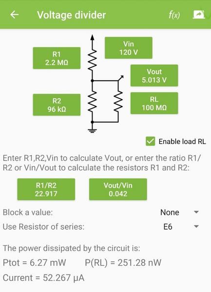
if i use voltage divider resistor 2.2MΩ and 96KΩ, then i use cap 100nF for the filter, so the time constant became how much ? 0.2 sec ? if it yes 0.2 sec, then what i must do at my coding, should adding the delay 200ms ?
thanks for the explanation.

Wawa:
That is ALSO adding over-voltage protection, which is not needed with a 1Megohm resistor in the divider.
Just a 100n capacitor from pin to ground is enough.

What value is the other resistor.
Are you using default Aref, or the more stable 1.1volt Aref.
Leo..

my resistor divider is 2.2MΩ and 96KΩ.
yes, i'm using default Aref, but i'm planning to using TL431 for external reference.
thanks.

Grumpy_Mike:
Let’s hope you are not making measurements of mains electricity.

You need two resistors to act as a potential divider not just one. That by itself is enough, no op-amp needed.

A standard technique is to take two readings and only use the second one. This allowed the internal sample and hold capacitor to charge up after switching to that input channel. In extreme cases you wil need to put a delay between the two readings to allow even more time.

yes, i'm using 2 resistor for making voltage divider.

about "take two readings and only use the second one", i did not fully understand, how to coding it...
is it like this ?

 for (int i = 0; i < 64; ++i) {
  analog += analogRead(A0);
  }
  analog = analog / 64;
  adc = (analog * 2.475) / 1023;
  voltage = (adc / 0.04125)*2; // 5Vdc / 120vdc = 0.04125
  delay(10);

for (int i = 0; i < 64; ++i) {
  analog += analogRead(A0);
  }
  analog = analog / 64;
  adc = (analog * 2.475) / 1023;
  voltage = (adc / 0.04125)*2; // 5Vdc / 120vdc = 0.04125

thanks for the answer.

PerryBebbington:
I assume you have 2 resistors in series, with the 1MOhm resistor to the 120V and the analogue input pin, and a much lower value resistor between the input pin and 0V. Contrary to what might seem obvious, the source impedance seen at the input is the 2 resistors in parallel, so a bit lower than whatever is the value of the lower resistor.

This is because from an impedance point of view the 2 rails of a power supply, in this case the 120V, are effectively shorted together, meaning that for impedance purposes the resistors are in parallel.

yes, i use 2 resistor.
ok noted, thanks.

MarkT:
For high voltages you have to worry about resistor voltage ratings, and often its wise to use a series
string of resistors for the high voltage part of the divider, eliminating the risk of a single point of failure too.

To divide 120V to 5V is a ratio of ~24, implying 1M and 39k values or so, which is only 37.5k impedance
seen from the analog pin. Still thats higher than 10k so a 100nF cap is indicated in parallel with the 39k
resistor. That's got a time constant of 100n x 37k5 = 3.75ms

Extra diodes aren't useful/needed as the 1M resistor is limiting any current to 120µA max, which
isn't going to stress the protection diodes on-chip.

You can use two 560k resistors in series in place of the 1M for extra safety.

ok, i see, if i use 2.2MΩ and 96KΩ for voltage divider,
then for the 2.2MΩ, better i use more resistor in series for making itu 2.2MΩ, i.e. 1MΩ + 1MΩ + 100KΩ + 100kΩ so the total is 2.2MΩ.
thanks.

see, if i use 2.2MΩ in series with 96KΩ for voltage divider,

You are using the wrong words and putting us off. These resistors form a potential divider although it might look it we do not say they are in series.

about "take two readings and only use the second one",

analogRead(A0);
analog += analogRead(A0);

It is as simple as that.

Or

analogRead(A0);
delay(100) // or what ever
analog += analogRead(A0);

You seem to be making heavy weather of this.

You are using the wrong words and putting us off. These resistors form a potential divider although it might look it we do not say they are in series.

my bad, sorry for my words, my english not good enough.
ok, i will replace that words about resistor in series (voltage divider).

analogRead(A0);

analog += analogRead(A0);


It is as simple as that.

Or


analogRead(A0);
delay(100) // or what ever
analog += analogRead(A0);


You seem to be making heavy weather of this.

about the code, which is better?
adding the delay or not ?,
thanks for answering it, i will try it.

A delay does nothing else than stop code execution.
Can use it if you deliberately want to make time-spaced measurements,
to average out ripple/noise on the source (smoothing).
But a delay won't do anything for pure DC measurement.
Leo..

Which Arduino are you using, and how are you powering it.
You are currently using the Arduino supply as reference, which is not good practice for voltage measurements.
Your voltage results are now depending on input voltage as well as on supply voltage.
Using one of the internal stable references of the Arduino, and calculating your divider for that, could give a better result.

If I would do this for an Uno, I would use a 10k resistor from pin to ground, and two 560k resistors in series between 120volt and pin. with analogReference(INTERNAL); added in setup().
Leo..

But a delay won't do anything for pure DC measurement.

But it will for high impedance measurements as it allows longer for the sample and hold capacitor to charge up.

This only applies when you read other channels, if you continuously read the same channel there is no need.

Grumpy_Mike:
But it will for high impedance measurements as it allows longer for the sample and hold capacitor to charge up.

Not sure about that.
I think the actual switch to connect the input to the SH cap is only on during analogRead, and does not stay on during delay. When I tested this a while ago I saw no difference in analogValues.
Leo..

Wawa:
Which Arduino are you using, and how are you powering it.
You are currently using the Arduino supply as reference, which is not good practice for voltage measurements.
Your voltage results are now depending on input voltage as well as on supply voltage.
Using one of the internal stable references of the Arduino, and calculating your divider for that, could give a better result.

If I would do this for an Uno, I would use a 10k resistor from pin to ground, and two 560k resistors in series between 120volt and pin. with analogReference(INTERNAL); added in setup().
Leo..

im using arduino nano.
internal reference (1.1v) if compare with external reference (tl431), which is better ?

You didn't answer all of my questions, and I don't know what your expectations are.
The internal 1.1volt Aref should be a lot more stable (not accurate) than the supply of a Nano.
I would try the internal 1.1volt Aref first before adding a 2.5volt external reference.
Leo..

Wawa:
Not sure about that.
I think the actual switch to connect the input to the SH cap is only on during analogRead, and does not stay on during delay. When I tested this a while ago I saw no difference in analogValues.
Leo..

The actual behaviour on the ATmega's is the analog multiplexer is updated a few µs (normally 4µs
IIRC) before the ADC samples the input, so that if you just changed pins, there is very little time
to charge up the sample cap, hence the requirement for low source impedance.

However thereafter the cap is attached to the current pin (untill the next change of analog pin),
so that there is plenty of time to charge up for subsequent analogRead()s on the same pin, even
more so it there is a delay (but not if you then read on a different pin).

So if you only ever read from one pin the 10k source impedance restriction can be greatly relaxed.