I settled on the IRF520N to control the LEDs for this project. In the future I will use dedicated LED drivers and boards to simplify everything but will use the IRF520N MOSFET to switch the already built LM317N constant current devices.
Prebuilt modules with the IRF520N are readily available for switching motors and LEDs so it seems like a reasonable choice.
Again, look at the data sheet. Look at the gate source voltage and current charts in the data sheet. When using a MOSFET with an Arduino it has been suggested to use a Logic Level MOSFET.
If you want to use LM317s simply because you have them is not really a good idea. This is why it is always suggested to build a working prototype on a bread board before even thinking about soldering or mounting components.
Back in post #10 I gave you an example of how I PWM drive a RGB LED. There are any of several ways to go about it. Note the resistor values used in series resistors. Note how the Green and Blue resistors are not the same as the Red.
No there is no definitive answer. None I am aware of anyway. Even if I did want a constant current source I would not use an LM317. If I really did want a constant current source I would use a newer more efficient better chip solution.
Thank you for the circuit suggestion in the project advice. This convinces me to avoid the sunk cost fallacy and start the circuit anew based on the information in the thread. Appreciate it.
Not if you use 6-pin RGB LEDs (not common anode/cathode).
One LED driver can power up to six LEDs in series (on a 24volt supply).
So you only need three driver for nine RGB LEDs (12-30volt supply).
Leo..
Thanks for the recommendation, but all three LEDs on one driver wouldn't let each one be a different color though right? Since they are not addressable, each color on each LED needs its own PWM pin, unless I'm missing something.
I don't see how an LM317 could work properly on a 5volt supply.
A blue LED and sense resistor could already drop 3.3volt + 1.25volt = 4.55volt. The LM317 is old technology, and needs at least 1.5 to 2volt for itself to work properly. That's a supply of 6-6.5volt minimum, and half of the power wasted as heat in the regulator + CL resistor.
Leo..
Thanks for the link, yes, I am going to drop the LM317s. I thought the guide from Texas Instruments showing the LM317 as constant current devices for LEDs meant they were good for that purpose. It seems they are in automotive applications but for just turning on at a constant rate.
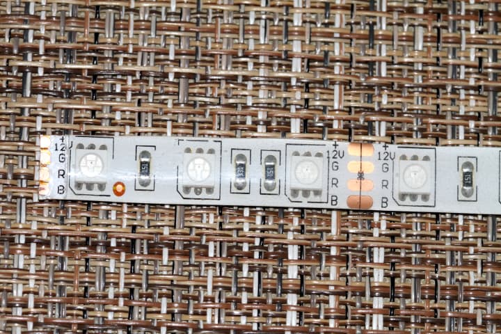
In this image each LED is a tri color LED RG and B and they are simply shown as groups of three LEDs in series with a current limiting reaistor. The strip can be sut to length.
You may want to Google "color picker" to get an idea of how colors other than RGB are made.
Very helpful. The strip LEDs have series resistors between each 5050 LED.
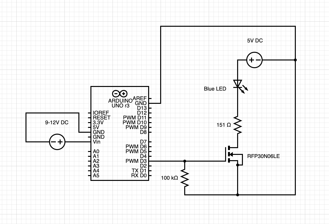
Based on your circuit drawing, I can hook up the FQP30N06 to the LED anode directly to the drain with a 331R or a 151R (depending on color) and connect the source to ground. The gate gets a 100k resistor to the GPIO pin. This also goes to ground?
I attached a drawing of how I believe the circuit should be set up. Is this correct?
