I have some 3W LEDs on the way, and I have a small project in mind which I want to do for a christmasy mood. It´s rather simple but I would still like to please ask for some help.
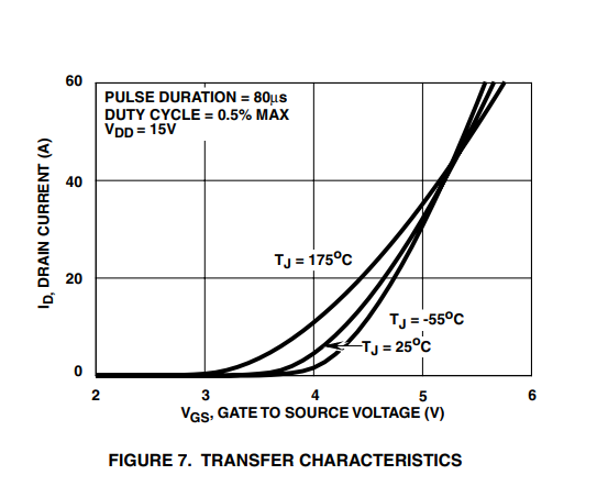
According to the sellers description, the LEDs have a forward voltage of 3.2-3.4V, and a forward current of 700 mA. Now I want to controll one LED with a Mosfet, simply because I already have them at hand. Mosfet is the IRF540N, and according to the datasheed at Vgs = 5V the drain current is aready up to 30A. Which is overkill of course but since I have them..might as well use them.
I would not use a dimming function for the LED (although curious if it´s possible with his mosfet), but I´m more interested to simply switching it on/off with some simple code.
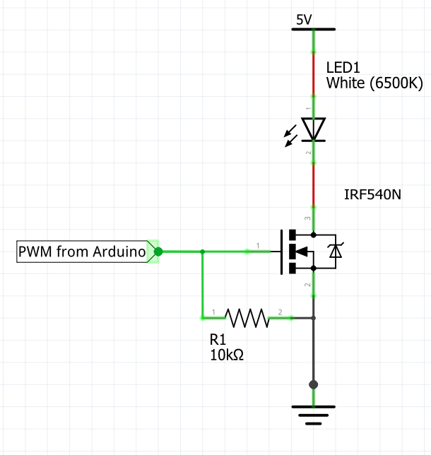
Now what I´m not sure of is, if this circuit will suffice..Is the resistor value OK? Should I need any more resistors, maybe a diode to protect the arduino etc...Any advice will be appreciated!
You certainly need a current limiting resistor in series with your LED.
Or some other constant current driver.
Should be fat resistor as it will dissipate more than 1 watt (depending on value chosen).
Marginal, but it should work for one LED. As mentioned, a current limiting resistor is required for the LED.
You should also have a 150 Ohm current limiting resistor between the 10K pulldown resistor and the gate (not between the port pin and the 10K pulldown).
We´ll I was thinking of using a 5V 2A power supply for the LED (would be only one) and the arduino.
But now Jim has got me thinking...then I would need at least a 9V 3A power supply, since I don´t need more than 1A from the mosfet, and I can use this to power the arduino as well through the Vin pin, and a LM7805 regulator for the LED. Can handel 1.5A of current accoriding to the datasheet, so having the current limited to 500mA with a 5W resistor throught the LED should be safe no?
You could also added an activ pulldown driver to control the MOSFET.
Because for high-frequency PWM, the passive pull-up makes the turn-on speed is too slow. If you oscillate too fast, the MOSFET spends too much time in turn-on and wastes too much power.
If no, by adding a resistor in series this will effectively limit the gate current, and therefore your switching speed, so this resistance should not be greater than absolutely necessary.
Hi,
I´m honestly not 100% sure what you mean by an active pulldown driver, do you have a schematics or example for reference?
And for the resistor in series, I assume you mean the 150 Ohm one...How can I calcualte the perfect resistor for the optimal switching performance?
I use 3W LEDs but use a Mean Well LED driver.
Variable input voltage, serial LEDs, PWM brightness and on/off digital line.
I use the LDD-L series. No heat. Little wasted power.
Not cheap. Just as an option.
I believe that's with an "infinite heatsink" holding the case temperature to approximately room temperature.
It will get very hot without a heatsink and it might get too hot even with a heatsink.
They are thermally protected and they try to shut down if they overheat so it shouldn't burn-up and die but they usually don't shut-down cleanly... They tend to oscillate and behave strangely...
The LED will also need a heatsink if it didn't come with one.
Work out where your circuit operates on it by extrapolating the V_GS=5V curve off the graph to I_D=0.7A and it will tell you info about the voltage drop across the MOSFET and its I*V=P wattage.
If you want to drive the LED at 500mA off of 9V, then you could skip the 7805 and do it directly with a different current limiting resistor: (9V - 3.2V)/0.500A=11.6Ohm at I^2*R=0.5*0.5*11.6=2.9Watts Maybe a 12ohm, 5W?
The choice of the value of this current limiting resistor is often ampirical, but in theory, depending on the gate capacitance and resistance of the FET, and the current capability of the previous floor (MCU).
For driving a mosfet, it is a solution like any other, it all depends on the characteristics of components, the voltages and the currents applied.
Here for very classic exemple with P-Channel Mosfet :
While I can appreciate you have a pile of IRF540N MOSFETS I believe you would do much better using a N Channel logic level MOSFET like a FQP30N06L or similar.
Thank you all very much for the help...Guess I really need to get myself either a new MOSFET or a led driver, hope I can get something in a reasonable time...Heatsinks will of course be used anyway, wouldn´t want to risk destroying anything
Under the specific test conditions and it is only a typical value.
You tell me what the max Rds(on) will be with Vgs=5V and with what degree of accuracy.