I bought my Arduino Mega a year ago and never started doing something with it. As a child I drew close to electronics but I never went past the basic principles and rules. Now I want to combine two passions. Aquariums and electronics just to have simple tasks automated. Nothing fancy, yet.
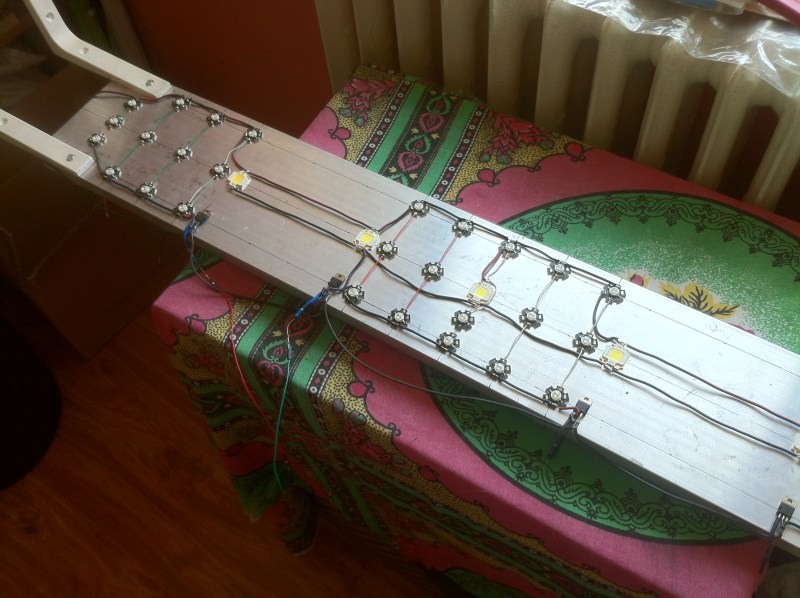
I saw there are a lot of people using Arduino to automate water changes, lights, pumps and whatnot to their aquariums but there is little explanation on how to build the circuits. Started out with the wealth of information on the Arduino site and experimented with different circuits until I got the basics right. Now I want to venture further with my project which for the moment is targeting at controlling the lights above a 80 gallon (300L) reef aquarium. The fixture is made by me out of 36 3W LEDs and 5 10W LEDs.
I'm planning on adding more light so I bought a switching power supply of 12V 16A for my project.
I designed the circuit so the LEDs are grouped in 4 channels all of them hooked to the PWM outputs from my Arduino. To control them I used a fairly popular and cheap power transistor (TIP122). The LEDs are glued to a large heatsink with thermal compound glue and also the transistors so that I can keep them cool.
The transistors are wired through a 1k resistor directly to the Arduino out pin and they are wired in the circuit on the -Vcc rail for each LED group.
The problem I think I'm facing now is circuit noise due to the PWM frequency. However, I tried putting decoupling capacitors with no success. The power supply emits a sharp noise that waves when the duty cycle is less than 75%. At full duty cycle everything seems to be working okay. The 10W LEDs tend to flicker a bit at about 10-15% duty cycle.
I have attached the schematic so far, bare in mind each LED represents an array of LEDs but for the sake of keeping things simple I've put just one for each channel.
Any help on what I might be doing wrong and how I can do this correctly is greatly appreciated. Also, note I don't have an oscilloscope.
There's a compromise to be made between low frequency (more flicker, much larger decoupling capacitors
needed on the power supply) and high frequency (less efficient switching, more problems with emitting RFI.
What decoupling do you already have on the supply? 16A will need a lot of decoupling I think.
I did read about PWM just about everything on the Arduino site. I haven't changed the PWM frequency. It's the standard 8-bit value that I write with analogWrite().
With regards to decoupling, I'm in the dark. I don't know exactly where to put the capacitors and how large they need to be.
Capacitor(s) between -Vcc and +Vcc rails before the transistors
Capacitor(s) after each transistor.
Capacitor(s) on each LED
The wires from the PSU to the transistors need to be long. I'm planning on mounting the PSU in the cabinet below the aquarium.
Any suggestions on how to quiet down the squeaking from the PSU? At the moment the maximum current draw is around 6A by coupling in series a digital multimeter.
With regards to thermal runaway, it's still a work in progress. With or without the current limiting resistors, the noise is still present.
Then read this:- http://www.thebox.myzen.co.uk/Tutorial/De-coupling.html
With that sort of power you will need big capacitors from the 12V supply to ground on each of your LED packs.
The bigger the better but at least 470uF on each light.
I assume that there is some sort of current limiting going on where you just draw an LED, if not there needs to be.
If they are 12V LEDs of the sort intended to replace MR16 halogen lamps, then it is not a good idea to PWM the supply voltage to them, because there will be a large capacitor across the supply pins. However, the current regulator chip built into the LED may have a separate PWM input, which you may be able to access.
The LEDs are 3W 3.2V-3.8V 700mA and 10W 9V-12V 900mA parts, China made. The PSU is a constant voltage one. I will need current limiting resistors but they are not mounted in the circuit yet. The first test revealed this problem I didn't took into account when I built the fixture. I'm asking for help in overcoming this issue not the current limiting flaw. A schematic with the required capacitors will help a great deal
The power transistors in the picture were removed and I have soldered them to a PCB pending the addition of components to deal with the PSU noise.
I will need current limiting resistors but they are not mounted in the circuit yet
No you do not need current limiting resistors. At these sorts of current they are useless. You need a constant current supply for each LED. Either as a chip or as part of a driver IC.
The power supply emits a sharp noise that waves when the duty cycle is less than 75%.
Tat implies that there is too much current being drawn. You need a very large capacitor to suppress these transients I would use a 1000uF or larger.
The problem is that the only schematic you have posted is only a partial schematic. You need a good design for your project.
Thanks for the details. This is the schematic I had in mind. I have made the required calculations for the resistors. The total current draw is not nearly close to what the PSU can deliver. Through each TIP122 does not flow more than 5 amps.
I need help with further making the schematic a working circuit as I'm over my head with this project I started. This problem is rather difficult for my skills in the electronics department. That's why I enlisted the help of this forum, to tell me what is wrong with this circuit. Thinking I'm not the first to be doing this sort of thing.