I am working on a guitar pedal foot switch that has a set of LED rings requiring 9V (5V won’t work. I tried). Each ring has two colors and one common ground.
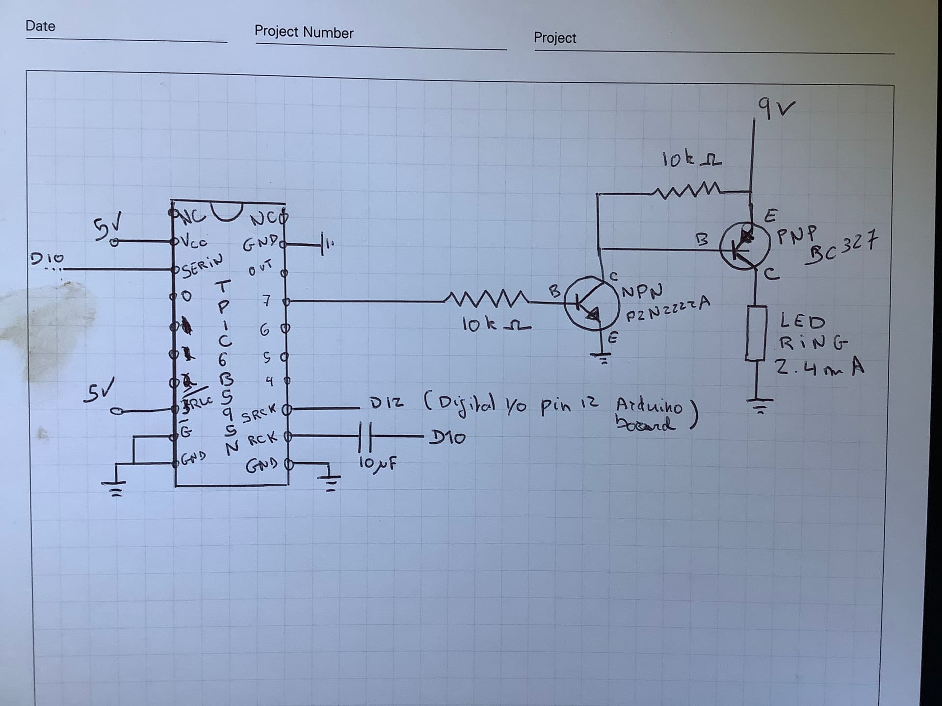
To control each color on each ring, I am using the circuit below. Basically a high side switch using two transistors (a N and a P) and controlled by a TPIC6B595 shift register (probably not required but it was available to me so I decided to use it instead of ordering something else).
The issue I am having is that despite coding to make the ring blink, the ring stays on all the time unless I touch the wire between the shift register and the NPN base. In that case, the LED start blinking as coded.
This is my first project using transistors. Any help would be great.
Thanks a lot
Could you stop using that circuit please ? It can be used for students: who spots the most problems. You may assume that some components are blown.
You have start again.
What do you want to turn on and off ? Can you give a link to the led rings ? Or can you make a photo of it ? Do they really need 2.4mA as you wrote in the picture ?
You need to put a 5k or so resistor between the NPN collector and the PNP base. When ON the base - emitter voltage in in the range of .5 to .7 volts. So in your circuit the NPN will try to make its collector a few millivolts above the emitter but the PNP is fighting it by not letting more than .7 volts from E to B.
I would guess the NPN would loose and burn up.
Is there a reason you must use a high side switch?
Thanks for your reply.
I will try your suggestion.
From what I understand I need to use a high side switch because the ring have a common ground between the two colors so I need to control the 9V. But I am a super novice with that sort of projects so I am not 100% sure if that’s true. That’s what I gather after reading a few posts.
That's right. Also the NPN transistor can be omitted because the TPIC already has open collector outputs that handle up to 18V(?) - see the data sheet.
That's because a resistor to Vcc is missing that can turn the NPN ON. You should read more about open collector outputs.
The problem is that each LED ring has two colors but only one ground. How would i control the second color if i drain the current from common ground for the first color ?
Then you can remove the first stage with the PN2222A, and let the TPICB595 drive the BC327.
You need a resistor between the shift register and the base of the PNP transistor, that was missing in your circuit. 10k should be okay for that low current.
I don't know if a resistor needed for the B-E, probably not. The leakage current of the TPIC595 is typical 0.1µA.