Hiletgo 5V relay module, flyback and powering Q

I'm using some of the prolific "hiletgo relay modules" you can find on amazon, etc (image below). I'm using the 5V version which claims to be optoisloated. It has 3 inputs, V+, V- and Input. The input appears to control the opto which in turn switches the V+/- to the relay coil. However I don't see any flyback diode on that coil. There's what appears to be a zeener in there but I think that's more for the LED indicator part of the circuit (not sure).

I can solder on a flyback diode, but wondered if anyone else had encountered this?

Also, I am powering a Mega board with a USB cable that provided power only. Long story on the whys for that, but I'm essentially using a the USB port as a power jack. I know the USB port is limited to 500mA. This relay module pulls about 70-80mA. I have 5 other (different) relays that are truly opto isolated and they are set to pull about 8mA max from their respective digital pins (40mA total on those). I have 2 servo style PWM outputs that control externally powered motor controllers, not sure what their current draw is. Not much I don't think.

My question is, is it a problem to power the Hiletgo relay module (V+/-) vi the 5V rail from the Mega? I'm using a breakout hat with terminals for all the Mega pins, so I have the extra 5V connection points..

Edit, actual module, in lieu of stock photo I used:
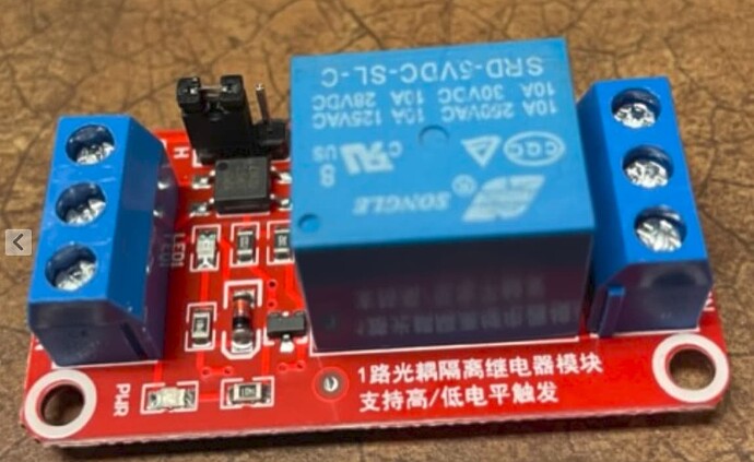
What makes you think it is a zenner? Led circuit does not require a diode, only a resistor. I expect that diode is the flyback diode for the coil.

The forum can't answer that without full details. You need to find out the current draw of each component, motor, relay, etc to ensure the total does not exceed 500mA, ideally less than 80% of that for safety.

Consider that motors can easily draw 5x their normal rated current at startup or if motor stalls.

You say you are using the 5V version of the relay module but the photo shows the 12V version. Are you sure which version you are using?

Why are you using relays at all? Could they be replaced by MOSFETs?

That depends on how YOU connect it.
This module has been covered not that long ago in another thread. Maybe you/somebody can find it. From memory, if you want opto isolation..., remove jumper, connect Arduino 5volt to middle pin, IN to an Arduino output, and DC+ DC- to a seperate 5volt supply. Don't connect Arduino ground to the module, because that would defeat opto isolation.

The little glass tube, next to the 3-pin transistor.

All opto isolated relays I know have an opto LED, an indicator LED and a 1k resistor in series, and "draw" 2mA. Don't rely on "fake" specs from sellers.

Don't power a motor (servo) from/through the Arduino. Even a small SG-90 draws a peak current of 650mA when starting move (or being loaded). Could be several amps for larger servos. Look in the datasheet for stall current (not running current). The supply must be able to handle stall, otherwise you could end up with a twitching servo.

One or two relay modules (~75mA each) would be ok. Four, maybe not.
Leo..

1 Like

I'm using 5V, my bad on the stock photo. It matches mine layout wise. The motors are not connected to the Arduino. Relay is for a solonoid valve, the module is for convenience, it's a high school robot project, prefer to not to be making PCBs. These modules are prolific and off-the-shelf.

if you want opto isolation..., remove jumper, connect Arduino 5volt to middle pin, IN to an Arduino output, and DC+ DC- to a seperate 5volt supply. Don't connect Arduino ground to the module, because that would defeat opto isolation.

My circuit is a 5V regulator that has a male USB cable wired to it's 5V output, that USB is feeding the Arduino via it's USB port. I'm getting 5V to power the relay from the "5V" pin on the Mega, which if I understand correctly is connected directly to that USB 5V in, no regulator etc between. So the 5V I'm pulling off for the relay module power is effectively coming from the 5V supply, I think. Only it's running through the Mega's traces and pins.

The little glass tube, next to the 3-pin transistor.

Thanks, I figured that was a zener based on it's color, being more uses to the black banded cases fro diodes. Zeners start pushing my electronics skillset, didn't know it could be used for flyback. However, looking at the traces, it doesn't appear to be across the coil leads without anything inbetween as I'd expect with a flyback diode.

All opto isolated relays I know have an opto LED, an indicator LED and a 1k resistor in series, and "draw" 2mA. Don't rely on "fake" specs from sellers.

I didn't. For those "other" relays, I removed the resistor they had in place for the Opto, and replaced with an appropriate resistor to ensure I had the opto current I wanted. Verified it was OK on the Opto's datasheet. And measured, tested to be sure.

Don't power a motor (servo) from/through the Arduino.

I understand. I am not. The PWM devices I'm controlling are dedicated high current motor controllers used in First Robotics. They are powered via external 12V. I'm only providing the pulse for control. They are designed to be controlled with a uP.

Thanks for the assist. Appreciate it.

If this is a robot then I don't expect any of the voltages involved are 120/240VAC. So the relays could easily be replaced by MOSFETs, which require virtually zero current to switch them on, unlike relays which require typically 60~80mA each. This could ease your problems significantly. Just because a component is common doesn't make it a good solution. What you have to understand is that relays are not technology from the last century. They are technology from the century before that.

Wanted or needed. How did you calculate that resistor.
I hope not with the absolute max rating of the opto LED.
Did you know the CTR of the opto used, and the required base current of the relay transistor.

2mA seems to be the standard.
1.2volt across the opto LED, 1.8volt across the red indicator LED, 2volt across the 1k resistor.
Leo..

Wanted or needed. How did you calculate that resistor.
I hope not with the absolute max rating of the opto LED.
Did you know the CTR of the opto used, and the required base current of the relay transistor.

This other relays weren't the intent of the OP, but I do appreciate your attention to them since I mentioned it. My target was to get the current down from where it was from being originally used with a 12V signal. With a R=570, it's currently measured @ 8mA ON with a 5V signal from Mega. The input LED rated at 60mA (max), 1.65Vf, CTR 40%min, 80%max. The Opto is a Liteon CNY17F-1. It is triggering the target relay (Tyco V2R-1001 with a coil R=150ohm, 80mA@12VDC)

If this is a robot then I don't expect any of the voltages involved are 120/240VAC. So the relays could easily be replaced by MOSFETs, which require virtually zero current to switch them on, unlike relays which require typically 60~80mA each. This could ease your problems significantly. Just because a component is common doesn't make it a good solution. What you have to understand is that relays are not technology from the last century. They are technology from the century before that.

Paul, thanks for the input. Transistors are the normal end of my circuit skills as I'm from the past century. I remember having trouble selecting a MOSFET a very long time ago for something unrelated. For the applications of switching 12 and 24VDC loads, less than an amp, probably less than 500mA, using 5V, what MOSFET do you recommend? A circuit pointer would be great, too since you are versed in them. I will investigate changing.

For smaller loads (<500mA), ordinary npn transistors like bc337 or 2n2222 will usually be fine. For higher currents, n-channel MOSFETs like irlz44 or stp36nf06l would be suitable. The important things when using MOSFETs with microcontrollers like Arduino is to select parts with a logic-level gate (Vgs < 3V) and a low on-resistance (Rds-on) with 5V or 3.3V on the gate, and to connect an external 10K pulldown resistor to the Arduino pin to stop the MOSFET gate floating as the arduino starts up. A current limiting resistor (e.g. 330R) between the Arduino pin and the MOSFET gate is also a good idea, especially if you plan use PWM.

1 Like

Paul, thanks, I'll get some to play with. Appreciate the suitable component numbers.

This topic was automatically closed 180 days after the last reply. New replies are no longer allowed.