I am trying to make a Christmas Countdown sign to hang outside. i have a mega2560. i am making two 7 segment number displays out of 12v strips. i order one 8 channel relay output shield and plan on ordering another. i also ordered the clock module. i am looking for the sign to start at 24 on december 1st and automatically count down 1 number each day. i think i have everything but i wanted to double check or see if anyone had any other suggestions? I am brand new to arduino but have a little back ground in basic stamp programming and building. thanks for any help anyone can offer me!!!
Which clock module?
By the way, I've done some date/time related stuff, in case you want to borrow code.
As for the 7-segment displays: you can save yourself a segment or two if you make an observation.
 ****    ****
     *  *    *
     *  *    *
     *  *    *
 ****    ****
*    *  *    *
*    *  *    *
*    *  *    *
 ****    ****
Notice I left out one segment. As long as the numbers you are displaying are all less than 40, you don't need that segment.
(I learned this trick from clocks that only need to go up to 23:59.)
Thanks for your quick response!!!! I ordered the RTC12C off ebay. I took a shot in the dark. I can always order a different one if need be. As far as the segments, i did take that in consideration. I built one of these before but used a serial controller connected to a computer. i have all the segments flashing randomly for about 3 seconds then the number would pop up. make it attractive and somewhat fun. if i order another output board i will have plenty for all 14 segments so that should be okay. as far as the code for the time, i would definitely be interested. id assume that i would have to create a program that would compare to the clock to see what day it was or something like that. i understand how it probably should work, but usually i need a little help to get it moving.
Ryanm0085:
if i order another output board i will have plenty for all 14 segments so that should be okay.
Count again: you don't need 14 segments.
With a bit of cleverness, you don't even need 13 segments. You only need 10 or 11 segments, though some "segments" will be composed of more than one segment, so you should adjust for this accordingly.
 !!!!    ****
     *  *    *
     *  *    *
     *  *    *
 !!!!    ****
*    *  *    *
*    *  *    *
*    *  *    *
 !!!!    ****
The three ! segments can be wired together and treated as one long segment. It will still draw three segments' worth of power, though, so you will have to allow for this.
as far as the code for the time, i would definitely be interested. id assume that i would have to create a program that would compare to the clock to see what day it was or something like that. i understand how it probably should work, but usually i need a little help to get it moving.
For your application, just check to see if the month is December, and subtract the day of the month from 25.
If November, then subtract the day of the month from 55.
If you want more clock / calendar stuff, please see the attachment. It is calendar stuff I used from a previous project.
If you are a beginner, you will probably need help understanding it, so please feel free to ask me.
By the way, I can't find much info on the RTC12C. Is it like the DS1307 or the Chronodot? For that, I think you will need help from someone other than me.
calendar-stuff.cpp (4.77 KB)
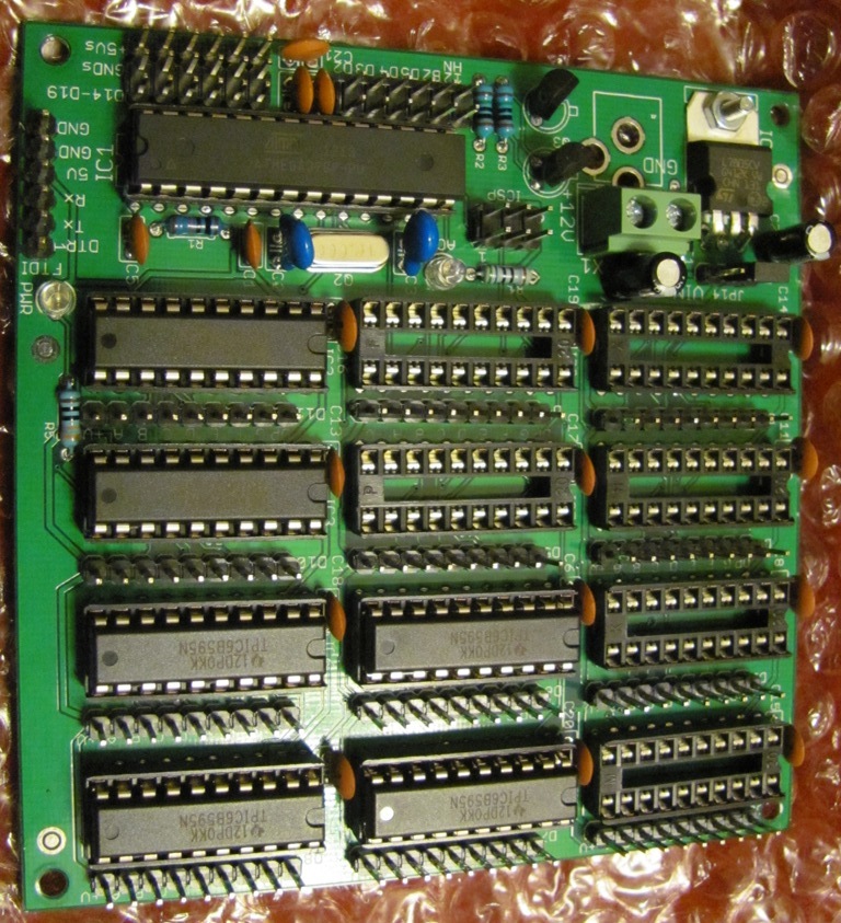
This board I offer was designed to drive 12V LED strips, up to 12 digits. Perfect for a countdown clock, just connect up an RTC module via I2C. Don't populate all the shift registers if you don't need all the digits.
Bootload via ICSP header, download a sketch the same way, or connect an USB/Serial module to download a sketch after bootloading.
odometer...i see what you are saying with the segments. makes sense. the clock module is the same as the ds1307. Thanks for the info crossroads. However, i dont think i am ready to jump into anything like that yet. I'm still getting familiar with everything and that seems far to advanced for me. I could be wrong though.
Attached to this post are a couple of sketches I've used.
These were intended for use with a Chronodot, but I believe they will work with your chip as well.
NOTE: in the clock_time_adjust sketch, you will need to put in the numbers for the date and time yourself!
Then, I suggest you use the readtime sketch to make sure the date and time were indeed set correctly. (You will need to use Serial Monitor to see the numbers.)
readtime.ino (1.88 KB)
clock_time_adjust.ino (559 Bytes)
Its just an arduino with integrated shift registers that can handle high voltage & high current.
If you are driving few enough segments, you could drive them with NPN transisors, or N-channel MOSFETs, from Arduino outputs to sink current thru your segments.
Or a couple ULN2803's. Or a couple TPIC6B595s. Or relays. Or ...