Can a crystal be replaced by anything that outputs A frequency? does it have to be constant, can it oscillate , like fade from 20 to 16mhz and back?
Because i was just pondering away, and my understanding of crystals maybe be totally off, but i was thinking what if you had some of those brain wave sensors and then wire that to pins 9 and 10 where the crystal goes on the 328p and if you load the blink sketch for example it obviously will not blink once per second but more erratically , my question is would it even blink at all?
Is a frequency simply highs and lows if so can i use another arduino to make a frequency using PWM and wire it to where an atmegas crystal would go?
Yes, you can drive the oscillator pins with something else. See Paragraph 8 of the data sheet. I believe you need a 0-5V signal, from 0-20MHz.
However:
"When applying an external clock, it is required to avoid sudden changes in the applied clock frequency
to ensure stable operation of the MCU. A variation in frequency of more than 2% from
one clock cycle to the next can lead to unpredictable behavior. If changes of more than 2% is
required, ensure that the MCU is kept in Reset during the changes."
I'm thinking maybe a better bet is to get a voltage controlled oscillator and use whatever to alter the voltage seen at the VCO to adjust the frequency instead.
Is a frequency simply highs and lows if so can i use another arduino to make a frequency using PWM and wire it to where an atmegas crystal would go?
Yes it has to be TTL logic levels, highs and lows. However a randomly variable clock signal would be possible, it that's really what you are after. If you really just want to simulate chaos in your program, just use the random() function, creatively.
Ah thanks I have to give that data sheet a look even if i dont understand half of it , not really looking to create chaos just wanted to better understand what the pins accept as a clock.
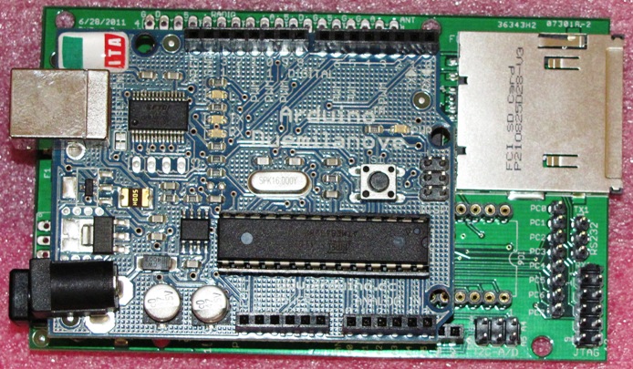
crossroads i was looking at the Bobuino rev 17, that thing is a beast!!
Yeah i read through the PDf and what you get for that slight difference in size is a lot more of options. I thought the RTC and Jtag where a neat addition
you can't just connect the PWM output to the clockinput! the resulting voltage of an PWM-signal is just the relation between on and off. the clock of an PWM-signal is fixed .
if you want to use an other arduino for a variable clock-source, it can only provide a variable voltage-output which can be used to control a voltage-controlled-oszillator.
eddiea6987:
Can a crystal be replaced by anything that outputs A frequency? does it have to be constant, can it oscillate , like fade from 20 to 16mhz and back?
m = milli (0.001)
M = mega (1000000)
Hz is the correct symbol for Hertz. 16mHz is about 1 cycle per minute.
But you are not alone, I've seen many datasheets getting such things wrong!
With the standard fuse settings the 328 is configured as a crystal oscillator, but it is possible to feed a logic signal into the XTAL1 pin via a 1k resistor, leaving XTAL2 unconnected. Seems to work fine (the oscillator circuit doesn't mind in my experience).