This is the one I found
This version does not have a series resistor for the backlight.
@emaayan where is your 2K2 resistor connected? Can't see it in your photos.
This is the one I found
@emaayan where is your 2K2 resistor connected? Can't see it in your photos.
you can't see in the photos because i'ts under heatshrink of the yellow wire..
i've hooked it up like that because i'm a firm belieber in components oriented approach, (lukcy too, because initially i've used a 22 resistor, honestly i think the industry would suck to anyone who's color blind ) so later i could re-use this components for the expansion board and soldier another transistor to the protoboard .
the voltage between collector and emitter is 2.1 v. (considering i have 4.65 , doesn't that mean 4.65/2.2 i'm drawing 2.2 amps?
What value is your series resistor when you measure 2V1 between collector and emitter?
What value is the voltage across the two LED connections?
Thanks.. Tom... ![]()
![]()
![]()
![]()
what do you mean between the two led connections?
So
Thanks... Tom.. ![]()
![]()
![]()
![]()
Hi,
Thanks.
Voltage across 22R = 4.56 - 2.1 - 2.4 = 0.15 V
Current through 22R = V / R = 0.15 / 22 = 6.8mA
So current through LED circuit == 6.8mA.
Check the voltage across the 22R it should be 0.15V
Tom.. ![]()
![]()
![]()
![]()
22 R you mean my 2.2k resistor?
Well say 2K2
Voltage across 22R = 4.56 - 2.1 - 2.4 = 0.15 V
Current through 2KR = V / R = 0.15 / 2K2 =0.000068A
So current through LED circuit == 0.068 mA. So no backlight I would say.
Check the voltage across the 2K2.
Tom.. ![]()
![]()
![]()
![]()
![]()
There are two resistors, one transistor and a LED involved.
Draw that simple schematics with values annotated to avoid this confusion!
Hi,
That's the base series resistor, not the LED series current limit resistor, what signal are you applying to it with the Nano?
Exactly what two points do you connect the red and green wire to on the I2C board?
Thanks... Tom... ![]()
![]()
![]()
![]()
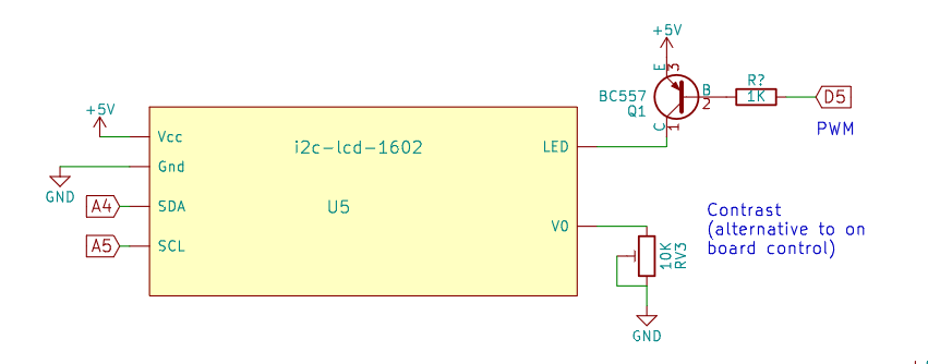
This is what I did to adjust the brightness of the backlight on an 1602 type lcd display with an I2C backpack. The led is connected to one of the two jumpered pins on the back pack.
In essence, the main points have already been discussed here (@PaulRB post #15).
This is much higher than it should be and may be causing your low brightness.
redwire goes vcc pin, green wire goes pin 15 which i believe to be LED+
i believe i did the same thing , only instead of BC557 I used PN2222 and instead of 1k R, i used 2.2k resistor.
Hi,
BC557 is PNP
PN2222 is NPN
Tom.. ![]()
![]()
![]()
![]()
yea i've been trying to read about the difference between them, and so far i undertsand NPN should sit on the negative side, and PNP should sit on the positive side.
unfortunatly i don't have BC557, i do have 2N3906,2N2907,2N2907A and 8550 transistors.
At least the 2n3906 would do in this case. It has a different pinout to the BC557.
Note also that in the case of that circuit, a higher PWM duty cycle means a lower backlight LED brightness.
that's that i'm reading here:
2N3906 Pinout, Features, Equivalent uses.
but now sure what it means " The 2N3906 is the most commonly used PNP transistor. It is almost similar to the bc557. the only difference is that it has a high collector-to-emitter voltage. This transistor is not suitable for amplifier circuits because it has only a gain value of 300."
still need to know what kind of resistor i need for it , i don't even know how to figure that one myself (yet), how to match resistors to transistors based on ciruite and specs.