I would like to design circuit by using above conditions and here's 4 more things to think about
• Use the current sensor ACS712 to read voltage and current of the load circuit
• Add 15 more loads and turn on an LED when the current is more than 2A
• Use a relay is break the circuit when the current is more than 2A
• LCD to display the Voltage in mV and Current in A
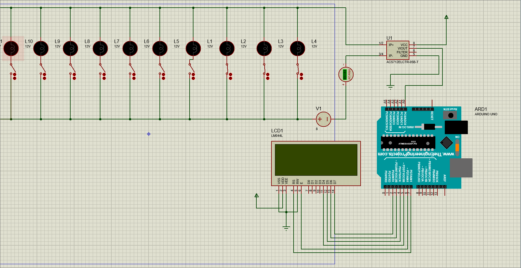
I will add screenshot of the circuit which I've made now. I'm not even sure that this circuit is correct or not though...So I want to get your advice.
For voltage measurement, you can't use the 712. You could use ADC on the Arduino. A simple resistor voltage divider brings down the voltage to something safe for the Arduino, an additional zener diode can be used for further protection if so desired.
If this is for circuit protection, I'd consider leaving the arduino out of the loop for this purpose and use a hardware latch (a simple opamp will do) to more or less instantaneously trigger a relay or so.
If you want to monitor 15 devices separately you'll have the challenge of getting enough adc inputs, but it's not entirely clear to me if you want to do this or if all loads will share a single voltage/current monitoring circuit.
The picture looks like it might work but is missing a few parts like power sources. I am assuming the loads are all connected to the source in a parallel configurations and your picture indicates. You are missing the relay, which you could use to turn on and off the loads but when you exceed the 2A and turn off how will you know when to turn it on again. LEDs need series resistors unless they are built in, which you sort of indicate by labeling as 12V. More information such as links to technical information on the hardware parts will help us help you. Also this looks like a classroom project so draw a proper schematic showing all connections. If you give us this information it will help us help you.
Thanks for your comment. By the way this was my mistake and after that I've designed a bit more of circuit from there. I will upload this screenshot together. Most of all our sensor-to-LCD system is working properly by showed us voltage and current through the arduino with code. But the weird thing is as you said it is classroom project but we'd never learn about using relay element to circuit. So that's also the point which I'd like to get some help from here. Can you give me some advice of adding relay circuit and LED on this screenshot's circuit?
Look online there are many tutorials that explain how to use the relay. Remember never connect the relay directly to the arduino it will damage it. Most of the relay boards have isolation in the form of a transistor or opto coupler, this will be shown in the tutorials. Number one rule: A power supply the Arduino is NOT! Give a schematic a try, you can get KiCad for free and it will take you all the way through PC boards if you want to go that far with your design. It has a fairly steep learning curve if you do not have experience with that type of software but you can do it. I will give you a hint, if there were a NO contact in series with V1+...
Of course if you say that it works, it works. However, if it works, you have not built it the way you drew the schematic. In your schematic, the ACS712 actually forms a short circuit that bypasses the Lx loads, the loads are effectively connected in series with your power supply (V1) and there is no connection that allows the Arduino to sample the voltage at the high side of the loads. I second the comment by @gilshultz; try drawing a proper schematic and see if you can make it accurately reflect the real setup you're working with.
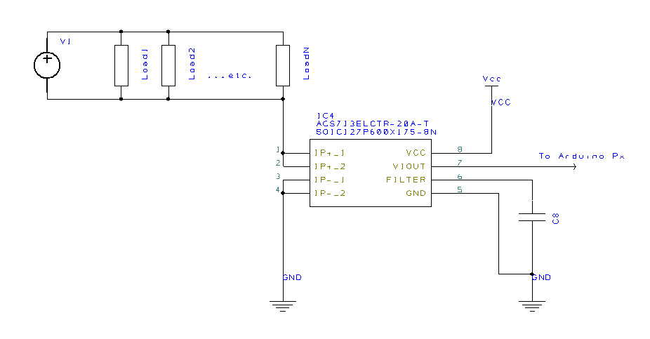
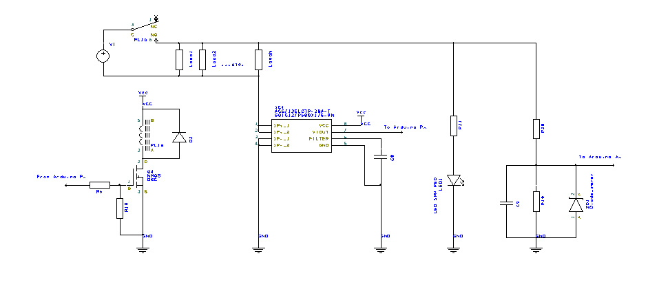
A schematic that would come closer to a working setup could look like this:
Note that I included a few components that you may or may not have thought about:
C8 is the filtering capacitor for the ACS71x that allows you to apply smoothing to its signal
D2 is the obligatory protection diode for the relay coil so you don't fry anything as the relay turns off
R6 is an optional gate current limiting resistor which is a matter of taste, but I like adding it
R18 ensures the relay isn't turned on if the attached pin of the microcontroller is either not attached or in high-impedance state
R21 is the current limiting resistor for the power led; calculate it using Ohm's law to set the desired current through the led
R19 & R20 form a voltage divider to bring the Load voltage to an acceptable/safe level for the Arduino to sample on one of its ADC ports
C9 (optional) smooths the voltage that's read by the Arduino so you don't get oddly fluctuating readouts
ZD1 is an additional protection of the voltage that goes to the Arduino's ADC pin to ensure it doesn't rise beyond a certain level; if your Arduino runs on 5V, I'd pick a 5.1V zener diode for this. The part is optional, but I like to include it
Yeah, it won't protect an unpowered Arduino against a voltage being applied to one of its pins. How would you handle that possibility?
Personally I just ensure in my circuits that the Arduino/microcontroller is powered always if the rest of the circuit is too. But I can imagine a more elaborate protection with e.g. a cmos switch as well. What would your preferred option be, out of curiosity?
Yes, clamping a shottky to the Arduino's Vcc could work, but I wonder if, to what extent and under which conditions it adds protection on top of the internal clamping diodes that are already present.
I do use CM1293's in many of my projects for similar purposes BTW, or occasionally a single BAT45 or MBR0520 if it's just one or two lines that need protection.
In my experience the Atmega328's internal clamping diodes are fairly rugged.
Yes, there were reports here of fully powering an Uno through an input pin (~50mA) without any harm. But the chip manufacturer does not want you to use them (it's not specified in the datasheet). I think they even took a .pdf offline where the clamping diodes were used to detect mains power zero-crossing. It's commonly accepted here that occasionally/accidentally clamping <=1mA is acceptable, although I don't know where that originated from.
Leo..
The series input resistor is a 1MΩ resistor. It is not recommended that the clamping diodes are
conducting more than maximum 1mA, and 1MΩ will then allow a maximum voltage of approximately
1,000V.
Any voltage higher than 1,000V would probably be spikes or surges. The clamping diodes are able to
handle spikes for a short period of time but not surges. The application note will not go into how to protect
against surges, but simply recommend implementing protection against surges in the design.
Consequently, if in my example schematic shown earlier the top end of the resistor divider is dimensioned to keep the current through it well below 1 mA, I would assume that the internal clamping diodes form a sufficient safety precaution.