Happy New Year
Please, how can I use this 3.5' screen on arduino mega ?

click on picture to see bigger.
pin number (32) is not the same as mega (36).
china vendor say "touchscreen for arduino mega".
Thank you
Happy New Year
Please, how can I use this 3.5' screen on arduino mega ?
click on picture to see bigger.
pin number (32) is not the same as mega (36).
china vendor say "touchscreen for arduino mega".
Thank you
By adding this STM32F407ZGT6-Development-Board-ARM-M4-STM32F4-cortex-M4 in between!
This display is the perfect match to the FSMC TFT connector of this STM32 board.
For Arduino MEGA you need level converters and a complex wiring to match the pinout.
You can look for TFT shields with level converters, but I don't know any with this pinout (didn't look for yet). So you would still need complex wiring.
ZinggJM:
By adding this STM32F407ZGT6-Development-Board-ARM-M4-STM32F4-cortex-M4 in between!This display is the perfect match to the FSMC TFT connector of this STM32 board.
For Arduino MEGA you need level converters and a complex wiring to match the pinout.
You can look for TFT shields with level converters, but I don't know any with this pinout (didn't look for yet). So you would still need complex wiring.
Maybe it will be easier to buy this one (same price)
https://www.aliexpress.com/item/3-5-inch-TFT-Touch-Screen-for-maga-2560-R3-Compatible-free-shipping/32314169615.html ?
Yes, buy the Mega2560 display shield. It plugs straight into the Mega2560.
There are several 40-pin Adapter boards for a Mega2560 but your 34-pin display does not match the 40-pin pinout. The Adapter provides 5V to 3.3V level shifters. You would have to hand-wire all the pins.
As far as I know, there are not any 34-pin Adapter boards for a Mega2560.
David.
ZinggJM:
By adding this STM32F407ZGT6-Development-Board-ARM-M4-STM32F4-cortex-M4 in between!This display is the perfect match to the FSMC TFT connector of this STM32 board.
For Arduino MEGA you need level converters and a complex wiring to match the pinout.
You can look for TFT shields with level converters, but I don't know any with this pinout (didn't look for yet). So you would still need complex wiring.
why would he need level shifters with the Arduino Mega2560?
The Display in the picture appears to have operating voltage of 5 votls.
the Arduino Mega2565 operating voltage is 5 volts.
The issue I see is having to jump the 34 pin connector to the Arduino Mega2560.
That is error prone.
If he were is use an Arduino Due than yes he would need level shifters
The display appears to have an operating voltage of 5 volts and the Arduino Due is 3.3volts
ZinggJM has given clear and accurate advice.
I have given accurate advice.
Please do not tell the reader that it s a 5V display when the photo clearly shows it is a 3.3V display.
David.
david_prentice:
ZinggJM has given clear and accurate advice.
I have given accurate advice.Please do not tell the reader that it s a 5V display when the photo clearly shows it is a 3.3V display.
David.
The photograph that I am looking at only has 5v label on one pin.
I see no 3.3v anywhere on the photograph.
So what am I missing?
You make these comments and provide nothing to go by.
I do not like your condescending tone and this is not the first time.
Also I was not addressing the user i was asking ZinggJM.
All TFT controller chips are 3.3V. None are 5V tolerant (as far as I know).
If you look at the pcb, there is no sign of any level-shifter chips (or series resistors).
The only i.c. is the XPT2046 Touch Controller chip.
Yes, there is a LDO regulator that will produce the necessary 3.3V (or 2.8V) for the controller.
But the logic pins require 3.3V logic. (3.3V is safe with a 2.8V controller)
If you see a pcb with several HC245 or similar buffers, it is probably designed for 5V logic. And 3.3V logic will work fine too.
If you see a board with several resistor-packs, it is probably designed for 5V logic. And 3.3V logic "works" too.
Note that visual inspection of a photo of a remote pcb requires guesswork. If a real pcb is on your desk you can follow traces with a DMM.
This is an Arduino Forum. Readers do not expect technical replies. At the same time there is a responsibility to provide accurate answers.
An Ebay Vendor does not care what she says. She just adds the magic word "Arduino" to any item whether it is appropriate or not. She does not care whether you fry 3.3V chips with 5V. It just means an extra sale (for another 3.3V device).
David.
artisticforge:
The photograph that I am looking at only has 5v label on one pin.
I see no 3.3v anywhere on the photograph.So what am I missing?
You make these comments and provide nothing to go by.
I do not like your condescending tone and this is not the first time.Also I was not addressing the user i was asking ZinggJM.
You are asking me? So this is the time to give you an answer.
I fully understand your motivation to post to this forum. But many of your posts are not helpful.
Please check yourself before giving an answer that might mislead any Newbie.
Be assured, you will be remembered.
ZinggJM:
You are asking me? So this is the time to give you an answer.I fully understand your motivation to post to this forum. But many of your posts are not helpful.
Please check yourself before giving an answer that might mislead any Newbie.
Be assured, you will be remembered.
That is not an answer that is a tirade.
I asked a civil question as to why that photograph of the display board is 3.3v.
There is nothing on the photograph that is labeled 3.3v. there is one pin labeled 5v.
So again I ask you, why is that display board 3.3v. How do you know that?
So far neither you nor david have given any answer to a valid question.
No more tirade and no more being condescending.
If you can not respond in a civil manner do not respond.
The next post will be some combination of...
From @iamnotgenius.
Directed to @iamnotgenius asking for more details.
Response to @iamnotgenius' question.
Good luck. The price for failure is high.
No it will be more tirades from one or both of them.
They will act all condescending about how it is obvious that it is such-n-such.
I doubt that they will be civil or behave in a civll manner.
@artisticforge, will be spending some time away from the forum contemplating the phrase "off topic".
thank you ![]() ZinggJM, david_prentice, artisticforge, Coding Badly for yours answers.
ZinggJM, david_prentice, artisticforge, Coding Badly for yours answers.
I can wire all pins on breadboard, and after go to local fablab for make my shield.
iamnotgenius:
I can wire all pins on breadboard, and after go to local fablab for make my shield.
thank you "i am not a genuis" for https://imgur.com, you are a genius ! (I do not know this website)
if fablab is too expensive maybe you can use theese
and read post here :
https://forum.arduino.cc/index.php?topic=490159.msg3344524#msg3344524
have you the wiring diagram and the library ? I can not help you for that.
@ moderator :
Please, can you clear or delete post out off my question, not helpfull, speaking 3.3V, etc ?
Thank you ...
@ mybrain_iq55
I have not the wiring diagram and I do not know witch library use.
If it is possible, I want try your solution https://forum.arduino.cc/index.php?topic=521034.0 - Album on Imgur that allows to use the screen bought instead of leaving it in a drawer.
Colour coded Dupont wires make life easier.
When wires correspond exactly, a flat ribbon keeps everything neat.
If you have to rearrange individual wires it gets unwieldy.
Yes you can make a custom cable with IDC connectors. Very easy with straight cables. Far more reliable than individual Dupont wires.
Rearranging wires and fitting in an IDC connector is a bit fiddly but if done correctly gives good results.
Buy a 17x2 Dupont receptacle and a 20x2 Dupont receptacle. Buy wires with ready-crimped ends for the receptacles. Make your custom cable. Mark pin #1 clearly on each end.
Any of these "solutions" mean Mega + Adapter Shield + multiple wires + Screen.
Personally, I would buy a Mega Protoshield, 24 level shifters and a 17x2 female header.
Hand-wire the TFT signals via the level shifters to the appropriate Mega pins e.g. D22-D37, D38-D41.
This gives a neat solution i.e. screen sits directly on the Protoshield.
But as you say in #2
. Maybe it will be easier to buy this one (same price)
https://www.aliexpress.com/item/3-5-inch-TFT-Touch-Screen-for-maga-2560-R3-Compatible-free-shipping/32314169615.html ?
David.
david_prentice:
Yes you can make a custom cable with IDC connectors. Very easy with straight cables. Far more reliable than individual Dupont wires.
Rearranging wires and fitting in an IDC connector is a bit fiddly but if done correctly gives good results.David.
Thank you very much.
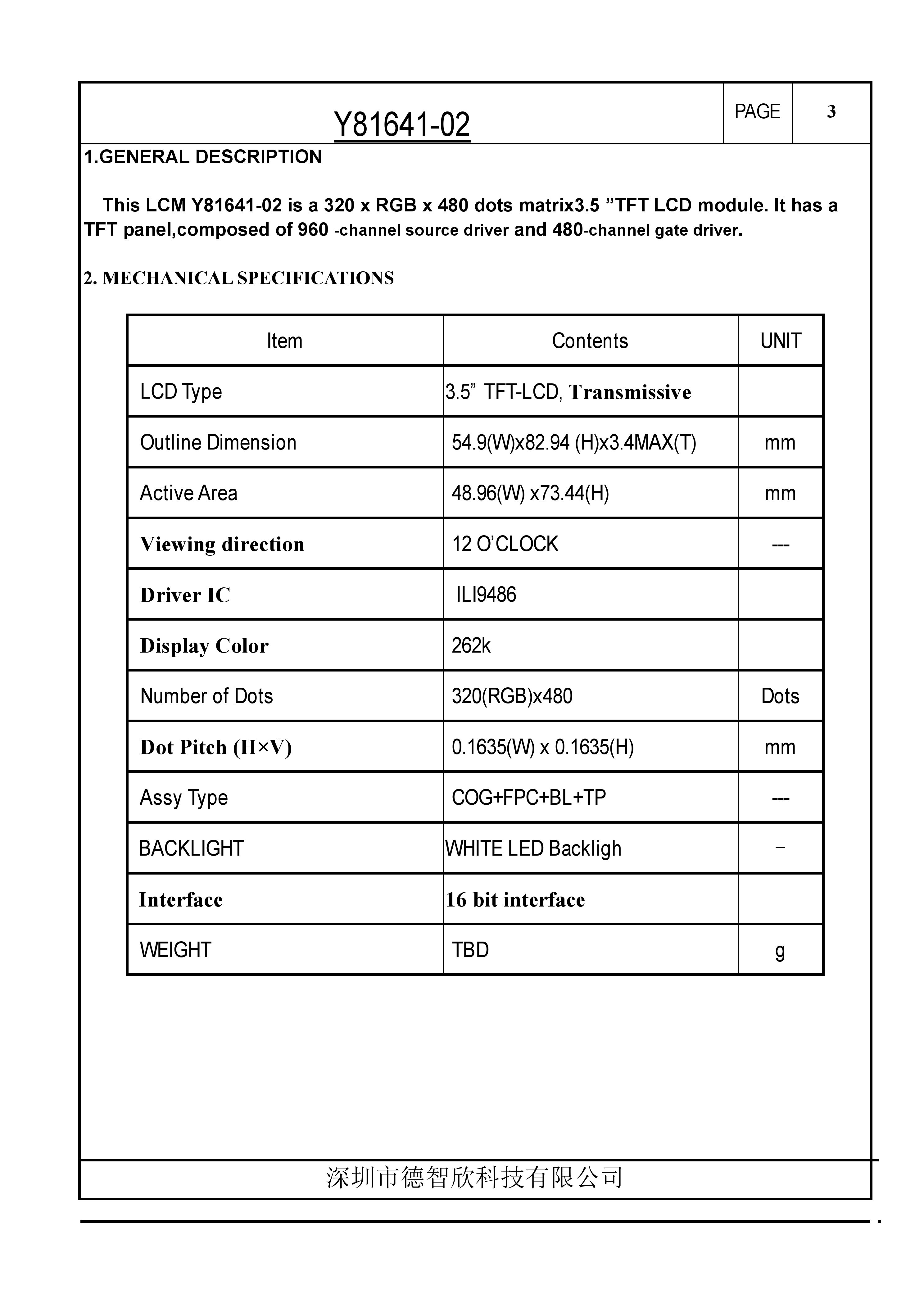
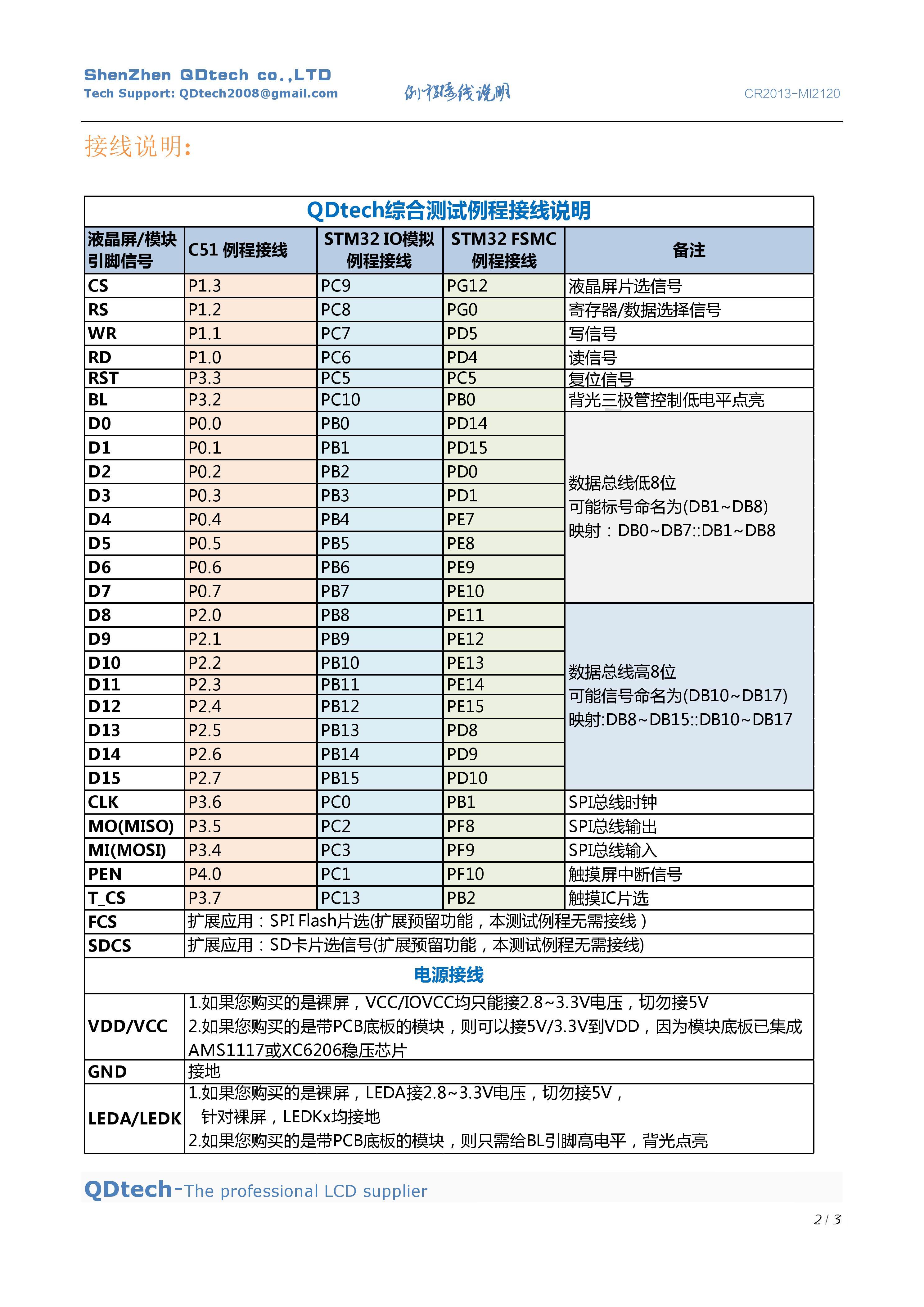
I just received several pdf files from vendor.
I convert all in 29 files jpg and you can see them on :
I think thees 2 pages are most important :
Maybe with theese data, you can help me about the wiring diagram between screen and mega and witch library use ?
You need to buy 3 or 4 level shifter modules or 74LVC245 chips.
You can mount them on a Protoshield pcb with a 17x2 female header.
Yes, there is a lot of work involved.
Buying a 40-pin Adapter Shield means you can use straight jumper wires because the Shield contains the level-shifter chips.
That Adapter has a 32-pin socket which does not match your 34-pin display.
Seriously, it would be cheaper and easier to just buy a Due clone or an STM32 board. These have 3.3V logic and hence do not need level-shifters.
I can help you with library software. When it comes to hardware wiring, you have to do that yourself. (I can tell you which display pin to connect to which level-shifter pin)
Your JPEGs say ILI9486 but then give data for HX8357-B
David.
Hi,
I have posted to your topic/question because I have this display on my desk, running on a STM32F407ZGM4 board.
I got it running without the need for additional information; but as you have got the information, I thank you for the link you have provided.
May I ask you if you could put this info into a zip file and add to your post? I do not know how to download from imgur.
Thank you and good luck with your project.
Jean-Marc
Hi David,
I have the same display, at least it looks like, and readID reports ili9486.
readReg info is posted here: Displays for STM32 boards with FSMC TFT connectors - #27 by ZinggJM - Displays - Arduino Forum
Jean-Marc