How do I get an Arduino Pro Micro to work with a 433Mhz RF transmitter or receiver?

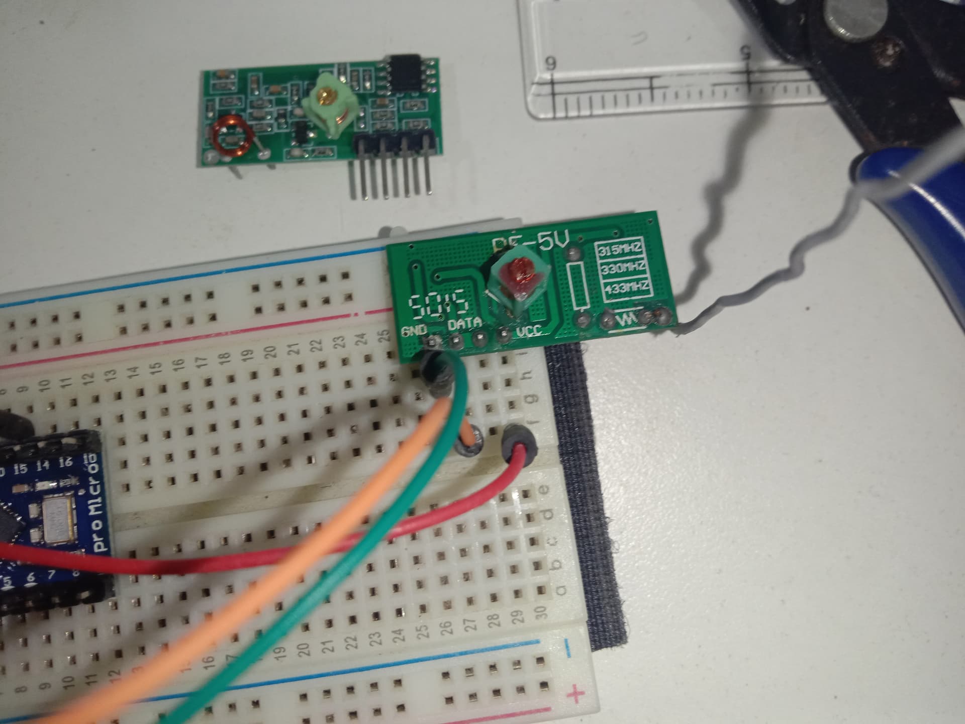
I've got two Arduino Pro Micros. One is wired to an RF transmitter, the other to a receiver.

Pin connections for transmitter to Pro Micro:
VCC to VCC
GND to GND
DATA to pin 5

Pin connections for receiver to Pro Micro:
VCC to VCC
GND to GND
DATA to pin 15

Code for transmitter:

#include <RH_ASK.h>
#include <SPI.h> // Not actually used but needed to compile

// Create an instance of RH_ASK with the specified data pin
RH_ASK driver(2000, 15, 5); // 2000 bps, RX to pin 15 (Just any unconnected pin should work right?), TX to pin 5

void setup() {
  driver.init();
  Serial.begin(9600);
}

void loop() {
    // message to send
    const char *msg = "test";
    driver.send((uint8_t *)msg, strlen(msg));
    driver.waitPacketSent();
    Serial.println("message sent");
    
    delay(1000); // Wait for a second before sending again
}

Code for receiver:

#include <RH_ASK.h>
#include <SPI.h> // Not actually used but needed to compile

// Create an instance of RH_ASK with the specified data pin for the receiver
RH_ASK driver(2000, 15); // 2000 bps, RX to pin 15

void setup() {
    Serial.begin(9600); // Initialize serial communication
    // Initialize the driver
    if (!driver.init()) {
        Serial.println("init failed");
    }
}

void loop() {
    uint8_t buf[RH_ASK_MAX_MESSAGE_LEN]; // Buffer to hold received messages
    uint8_t buflen = sizeof(buf);

    // Check if a message is received
    if (driver.recv(buf, &buflen)) {
        // Print the received message
        Serial.print("Message: ");
        Serial.println((char*)buf);
    }
}

I tried wiring the transmitter to an Arduino UNO with the default pin 12. I'm getting "message sent" in the serial monitor but not seeing anything in the serial monitor of the Pro Micro on the receiver side. And yes, I already tried both data pins on the receiver, no luck. As for range, I have a 17cm solid core copper wire connected to the antenna pin on both modules. Literally twisted the antennas together, both Arduinos being powered from my computer's USB port. Should be more than enough power.

I know both the transmitter and receiver work when using an Arduino Uno on both sides with the default pins for DATA. If I remember correctly they work when I assign a custom pin for both of them too. I will test it again to make sure if requested.

  • Always show us a good schematic of your proposed circuit.
    Show us good images of your ‘actual’ wiring.
    Give links to components.

Or too much.

Why can't you use the default pins, the same ones that worked on the UNO?

What is the Vcc on the Pro Micro?

Are you powering the radio modules the same way you did with the UNO?

To eliminate the possibility of a broken TX or RX, arrange a common ground between the two microprocessor boards, and wire the TX on one to the RX on the other with a resistor , value not critical, 1K to 10K is fine.

And yes, repeat your UNO experiments, do that with the wired (resistor) wireless trick.

a7

  • do not keep transmitter and receiver too close ( the receiver could saturate ), keep at least the tx on one side of the table and the rx on the opposite side.
  • if you have an oscilloscope, logic analyzer, something to sample pin 5 of your transmitter board do you see the 'train of pulses' every second ( same on the pin 15 of the receiver )?
  • does your boards ( arduino, tx and rx ) work at the same voltage?
  • also ( as already suggested ) try the null-modem connection ( do not connect the rf circuits, connect the gnd of both arduino and the pin 5 on transmitter to pin 15 of receiver )

Thanks for all the advice. I will try them all and report back to each comment.


I can not take pictures of the transmitter side clearly, but I confirm that the schematics are correct.

Pro micro has 5V and 3.3V variants, did you check yours?

5v. I've used 3.7v with an Arduino Nano and the same RF modules before anyways. 3.7v works fine.

If you knew what an Arduino Pro Micro is, you would know that there are no pins for either 12 or 11, which are the default RF pins. I will try your suggestions soon.

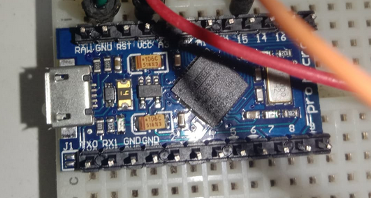
Are the header pins in the picture below actually soldered the Pro Micro? If not, don't expect the breadboard connections to be reliable, or work at all.

Capture

That doesn't mean 3.3V works.
5V device might work down to certain voltage x, more or less reliably.
Anyway, not relevant here.

A good suggestion, and the correct one! A simple, yet very helpful comment.

Thank you, everyone, for your help. Everything worked fine already, just that my wiring method was terrible.

I appreciate your help, after using my oscilloscope I can confirm there is a pulse on both sides from the Arduino Pro Micro. I will use the oscilloscope more often from now on.