Hello guys, I recently got a second arduino uno and got a radio module that I assume to be like a generic 433mhz receiver but it has a lot more pins than the ones I see online and I cant seem to find any tutorials for it
It came with a datasheet that explained what the pins did
So I tried to wire it up and used the example code from the radiohead library (ask receiver and transmitter)
The receiver circuit has it being connected directly to the arduino 5v and ground pin, I also attached a coiled wire at the pin labelled ant
For the transmitter circuit, I used a 9v battery to power the transmitter and the arduino(using the VIN and ground pins). I assumed that I the rf output pin is the antennae so I also attached a coiled wire on it
I changed the example code for radiohead ask_transmitter/receiver to both use pin 4, I connected the receiver arduino to my pc and attached a 9v battery to the transmitter circuit, but when I looked at the serial monitor, nothing seems to pop up, the receiver arduino also does not seem to blink its led. I have tried flipping the transmitter and receiver boards so I do not think i messed up the orientation for the pins. Can someone please help me identify the problem? I have been stuck for quite a long time on this

I didn't read to the end. Two things have to change before anything else. Put the 9V battery back in the smoke detector, that is all they are good for. Either power with your PC USB cable or a 5VDC wall wart. If you eventually need to go off grid, then either a USB powerbank or two 3.7V 18650 Lithium in SERIES ONLY.
Now try it again and next time post ALL the code in code tags also post any serial output in code tags. A photo of a hand drawn diagram of YOUR wires is also needed.
Welcome!
If you had gone through the last few days of this forum postings you would have found this:
Power Stability Issues with RF24 Radio Modules
As described in the RF24 Common Issues Guide, radio modules, especially the PA+LNA versions, are highly reliant on a stable power source. The 3.3V output from Arduino is not stable enough for these modules in many applications. While they may work with an inadequate power supply, you may experience lost packets or reduced reception compared to modules powered by a more stable source.
Symptoms of Power Issues:
- Radio module performance may improve when touched, indicating power stability issues.
- These issues are often caused by the absence of a capacitor, a common cost-saving omission by some manufacturers.
Temporary Patch :
- Add Capacitors: Place capacitors close to the VCC and GND pins of the radio module. A 10uF capacitor is usually sufficient, but the exact value can depend on your circuit layout.
- Use Low ESR Capacitors: Capacitors with low Equivalent Series Resistance (ESR) are recommended, as they provide better power stability and performance.
- Be sure the transmitter and receiver are at least a meter apart, more is better.
Adding the appropriate capacitors can greatly improve the reliability of your RF24 module by ensuring a stable power supply, thus minimizing packet loss and enhancing overall performance. A separate power supply for the radios is the best solution.
I note a couple of problems. First is the antennas need a straight wire, not coiled. Second, the documentation gives a range of possible frequencies for the devices. How did you ensure they operate on the same frequency?
Coiled wires can serve as an antenna.
But they need to be tuned to the radio frequency.
Antennas from straight wires can easily be tuned by cutting at 1/2 or 1/4 wave length.
Don't know how to do that with coils, but if the coils came with the radios, they are probably fine.
In general you can't transmit and receive on the same frequency at the same time. This is because the transmitted signal swamps the received signal.
I was once involved in the design of a Ham Radio repeater in the 420 to 450 MHz band (70 cm). The transmit and receive frequencies were separated by 5 MHz. Even at such a wide spacing the transmitted signal made the receiver very insensitive, to the point it would not work.
We had to use UHF notch filters in both the transmit side, tuned to the receiver's frequency, and another one on the receiver, tuned to the transmitter's frequency.
These UHF notch filters are simply tubes about the size of a bottle of wine and are tuned by adjusting a screw thread with a plate on the end to form a resonant cavity.
Please post the actual code you are using for both Arduinos.
The Radiohead library will def handle this simplest of radio sets admirably. As you are using one transmitter and one receiver, there is no problem with the frequency, as long as the set was sold as a pair. There is obvsly zero problem with multiple sources of the RF signal
Yes, lose the 9 volt battery! And use straight wires for the antennae at least for now.
A trick you might try which will remove software issues to a great extent is to
- arrange the two Arduinos so they are close
- make the ground connection common to both
- connect Tx from the transmitter Arduino to Rx on the receiving Arduino with a 1K resistor
Until that setup functions identically to how you hope it will when the wire is replaced on each end by the appropriate part of the radio sets, it is not productive to mess with this - you won’t have much way of knowing if it’s software or hardware or RF hanging you up.
When you move to using the radio sets, separate the receiver and the transmitter by a few meters.
I hate to say “good luck” as luck should not be a factor. But most ppl have a bit of a struggle with this at the beginning, no matter they use a primitive radio set like this one or something more modern.
You may want to just use something more modern, but TBH these cheap radio sets can be made to work very well, standard issues are power supply, antennae, frequency and code. The code part is the easiest, Radiohead as I have said is def a way to go if you aren’t into hand-making the code yourself. These 433 modukes and their ilk are fairly easy to code but do drsg you over some things you don’t really need to care about.
a7
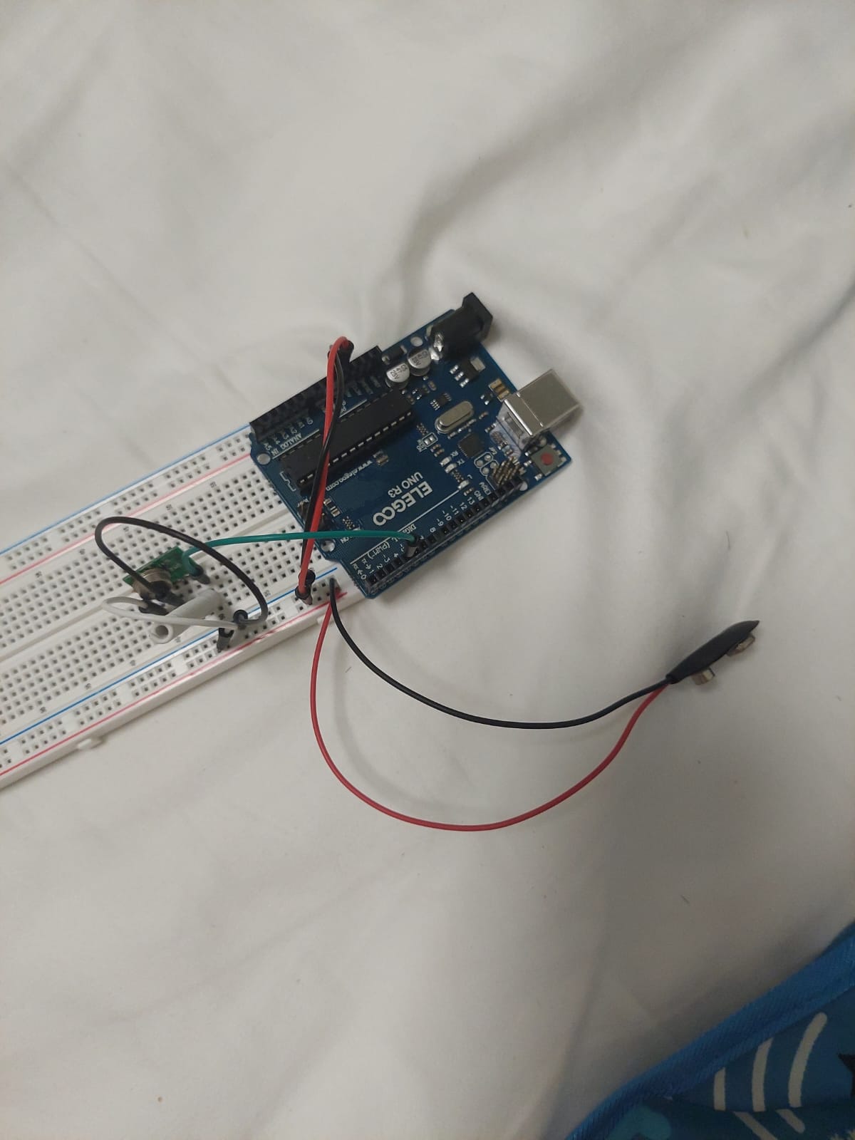
here is the diagram of the circuits
the code for the transmitter
// ask_transmitter.pde
// -*- mode: C++ -*-
// Simple example of how to use RadioHead to transmit messages
// with a simple ASK transmitter in a very simple way.
// Implements a simplex (one-way) transmitter with an TX-C1 module
// Tested on Arduino Mega, Duemilanova, Uno, Due, Teensy, ESP-12

#include <RH_ASK.h>
#ifdef RH_HAVE_HARDWARE_SPI
#include <SPI.h> // Not actually used but needed to compile
#endif


// RH_ASK driver(2000, 4, 5, 0); // ESP8266 or ESP32: do not use pin 11 or 2
 RH_ASK driver(2000, 3, 4, 0); // pin 4 transmit
// RH_ASK driver(2000, PD14, PD13, 0); STM32F4 Discovery: see tx and rx on Orange and Red LEDS

void setup()
{
    Serial.begin(9600);

    if (!driver.init())
#ifdef RH_HAVE_SERIAL
         Serial.println("init failed");
#else
        ;
#endif
}

void loop()
{
    const char *msg = "hello";

    driver.send((uint8_t *)msg, strlen(msg)+1);
    driver.waitPacketSent();
    delay(200);
}
code for receiver
// ask_receiver.pde
// -*- mode: C++ -*-
// Simple example of how to use RadioHead to receive messages
// with a simple ASK transmitter in a very simple way.
// Implements a simplex (one-way) receiver with an Rx-B1 module
// Tested on Arduino Mega, Duemilanova, Uno, Due, Teensy, ESP-12

#include <RH_ASK.h>
#ifdef RH_HAVE_HARDWARE_SPI
#include <SPI.h> // Not actually used but needed to compile
#endif


// RH_ASK driver(2000, 4, 5, 0); // ESP8266 or ESP32: do not use pin 11 or 2
RH_ASK driver(2000, 4, 3, 0); // pin 4 receiver
// RH_ASK driver(2000, PD14, PD13, 0); STM32F4 Discovery: see tx and rx on Orange and Red LEDS

void setup()
{
    Serial.begin(9600);

    if (!driver.init())
#ifdef RH_HAVE_SERIAL
         Serial.println("init failed");
#else
        ;
#endif
}

void loop()
{
    uint8_t buf[RH_ASK_MAX_MESSAGE_LEN];
    uint8_t buflen = sizeof(buf);

    if (driver.recv(buf, &buflen)) // Non-blocking
    {

        // Message with a good checksum received, dump it.
        driver.printBuffer("Got:", buf, buflen);
        Serial.println((char*)buf);
    }
}
It started to work after I moved the transmitter and receiver further apart, thanks guys  just out of curiosity, can I know why they do not work when they are too close to each other and why 9v batteries are not recommended?
9V batteries cannot provide sufficient current.
5V pin is also not recommended for radio modules...
Too close may cause signal transfers that do not go through the radio reciever... also known as emi.
Because of the reasons I told you about in my post #6.
Yeth.
One of the several many things that catch ppl up. Now your real fun can begin.
That nine volt battery works and is supplying sufficient current, evidently, but there’s not much power stored in there and even if it works, the Arduino will drain it perhaps a bit faster than you’d like.
Where did you get the length 30 cm for your wire antennae? I won’t say it’s wrong, but it isn’t what is recommended so I’d like to know who sez.
The figure 17.3 cm (173 mm) comes up for reasons.
a7
the recommended length written on the datasheet was 30-35cm, it seems to also work coiled.
OK then.
You may find that when you try for any significant range the antenna design will come back to be an area worth investigating.
In your deployment, what range are you hoping to attain?
a7
I just wanted to use it to make an rc car so that i could use the motors from one of my broken rc helicopters lol, from what i tested my current set up can already receive across my entire room so I think that it would be enough, although Im kind of curious how far it could actually go theoretically