I'm a little confused by your response.
Do you want PWM to 4-20mA or 0-3.3V to 0-20mA?
The topic is voltage to current limiting.
If you attach a multimeter on a pwm pin on an arduino. Say it is the 5v type. Pwm the pin with 25% duty cycle, will you see 5V or 1.25V?
The mcu is pulsing 5V but you will see around 1.25V, the multimeter is a slow measuring device with LPF so the average is on display.
Do not worry about if it is a pwm, the mcu is not capable of outputting a steady clean variable voltage in most cases, but it is the only thing I have, the signal is cleaned a bit with low pass filter and then we have a variable voltage, could be a little dirty but we will call it a usable variable voltage.
Buy one and reverse engineer it.
Tom.. ![]()
![]()
![]()
![]()
Hi,
Have you tried any circuits to see if they do the job?
Have you built a LP filter to see how the output looks.
Do you have a scope?
Have you tried the current converter circuit I posted in post #21?
Tom.. ![]()
![]()
![]()
![]()
PS. What is the custom sensor you have made/use?
So now you just want to convert a 0-5V signal to 4-20mA, correct?
Forget about the PWM and the 3.3V
No, still in the 0-3.3V world, but yes forget pwm, treat it as analouge voltage.
The arduino example was just for a simple calculation of 25% pwm.
I have arduinos on hand but use mostly rp2040 and esp32 now, and they are 3.3V
ESP32 has two DACs.
Tom.. ![]()
![]()
![]()
![]()
-
Not tried the voltage to current thing yet, but have made a lot of pcb's and stuff for my self and for my workplace
-
See 1, but have a picoscope, smd soldering things, lab power supply..
-
EC sensor, O2 sensor, salinity sensor, algae sensor, capacitive spectrography sensor (want to make H2S sensor too and CO2 in water and nitrates)
Capatance spectrography, testing hardware

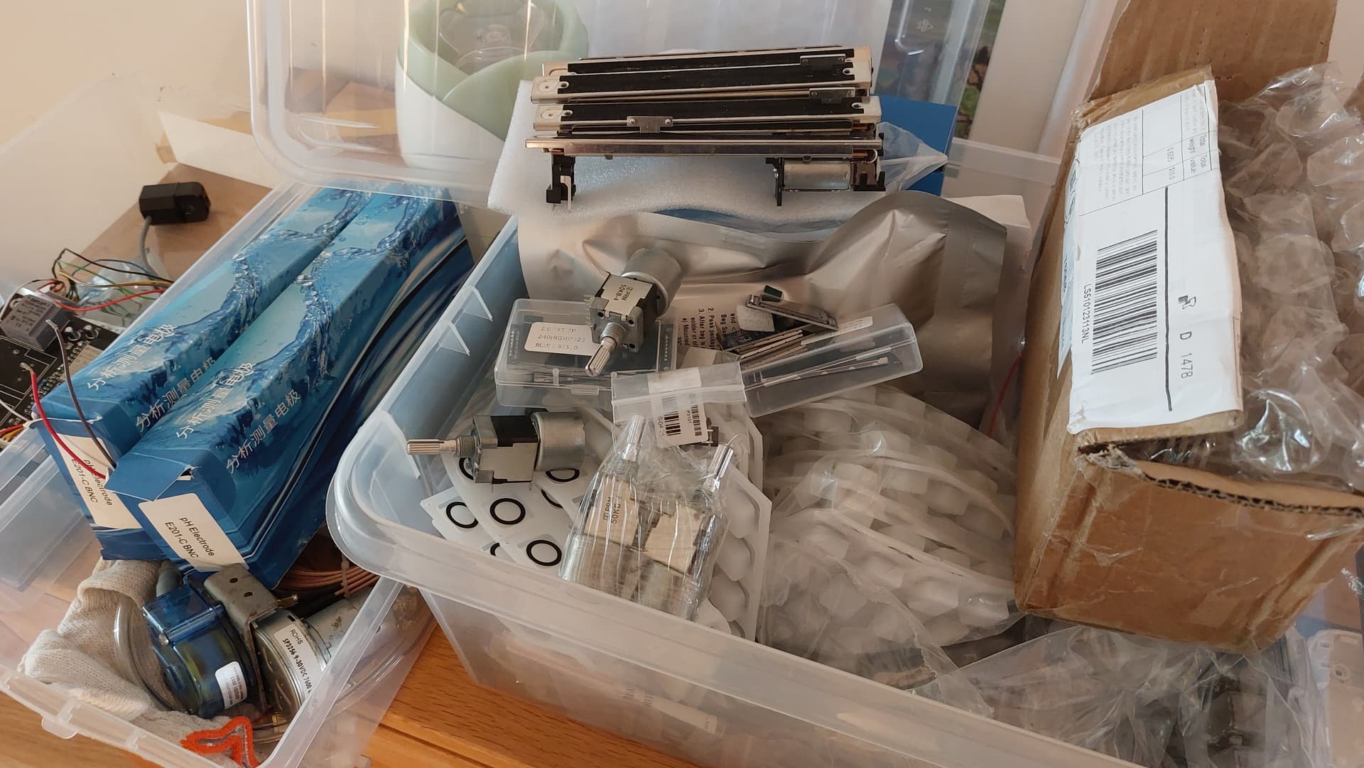
This is the summer and autumn projects box
Motorized faders, neopixel buttons, a lot of tft screens, audio mixer chips and potentiometers and rotary encoders, ph sensors from china, pumps and motors
So in all, mixer and dmx rack and sequencer and then water quality sensor project, leftmost is a part of second iteration of my EVSE Car charger
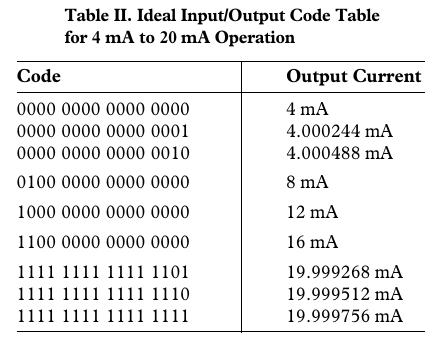
How about an AD421, send a 16 bit number from MCU via SPI, get a variable current (can be 4 ~ 20mA) out.
This is a $20 chip, so rather not, I am looking for the cheapest solution, not the most convenient if it makes my boards too expensive to make, this means that the price of 10 boards is in the 300 USD range, and I rather not spend that amount if I absolutely do not have to
DAC161P997 Single-Wire 16-bit DAC for 4- to 20-mA Loops
is more like that I want, but it is still $6 chip, but it is packed with features like HART communication interface if using the right hardware.
I have worked too long in engineering for manufacturing, and manufacturing is about do things that meet the specs at a specified cost, this is kind of engineering sport, hunting for the components that do things at an unbelievable low cost but still meet the spec.
you have to start near the rock bottom, test and if it is too bad, then go one step up or do something mindbendingly clever that makes the circuit work.
It is harder to go the other way and from the golden standard with all the bells and whistles, protection from lightning and your grandma and the ugly kids next door and every user errors that can be made from yesteryear to the heat death of the universe. people get comfortable and you get some crazy standards down your throat that are not relevant in 99.999% of the time and the consumer is stuck with overpriced and over engineered product. The project manager will be happy that engineering finished the product early for the once in a blue moon but sales is having a hard time pushing the product to the customer if it is not unique enough
The hunt is on!
But thanks for the tip
What temperature range, resolution and precision do you need?
Would an all analog solution not work?
temp from -hel to +hell ![]()
no, but living in norway -20C -> +50 can be considered a ok start, +60C inside enclosure in the sunlight is not uncommon
+4C to +20C is probably the most usual operating for the ebb&flow system, and the jacuzi is around +40C all the year, water well health monitoring system will be outside all year long, as is the jacuzi
As for resolution, 12bit is nice, 10bit is ok, 8bit is beyond horrible
Analog solution is probably perfect, the front end sensor is analog that is digitized 12b to the MCU and then it needs to be converted to analog current limiting loop for the plc and then the plc will digitize it again and put it on display in the automation system ![]()
Thermistor? Thermocouple? RTD? Linear temperature to voltage sensor like LM35 or TMP36?
None of those, water quality sensors mostly, but all the sensors have temp sensors to compensate from ideal behavior.
See post #50.
I often use rtd or dallas for temp, and I am just using a resistor and a super cheap opamp for gain to read rtd if I have one half of a chip at hand, if I do not need to be within .5 degC because let's face it, +-1°C is not catastrophic in majority of designs.
This is not for one off project, this is for a building block in my project library, a lego block of working circuitry, like I have been doing a lot of different pressure sensing experiments, then a loadcell block was made, was doing a lot of modbus things, then a rs485 block was made, was doing a few current sensing project with a current clamp, made bourne resistor block with voltage bias, was working with pH sensors, needed instrument amplification, made opAmp circuit for that, is now a building block costing less than 0.2usd to add on the pcb that I am making, good luck finding a decent ready made pcb for under $10 for a pH sensor amplifier, small transistor blocks to turn on bigger mosfets or relays.
Not all are super usefull in all cases, but nice to have, sometimes it is nice to have inrush current limiting sometimes it is way overkill.
But to be able to cut and paste from a library in your pcb design software is golden, granted, the out of stock part replacement is a bit time consuming but you hit the ground running being able to put whole circuits at a time on the schematic.
And because I usually blow up the first 3 versions, I want to have everything throwaway cheap to be able to afford the iterations, you are crazy if you think the first version is the final one, no routing error, no mislabled component, no mirrored footprint, no trace too thin, no wrong values on passives...
Best of luck, don't give up.
Hi,
What is your target market?
What is your target selling price?
Thanks.. Tom.. ![]()
![]()
![]()
![]()
Thanks , I had serious doubts about my reading skills , now I can carry on with my life.
No target market, I would have to quit my job to sell some of my work.
It is too much hassle to start a company and begin being a seller for hw. Too unsure income, but we will see in a few years
Allthough, some of the things I have made have been for work, like the algae sensor. That was a one year project, a lot of man hours, I had to grow several types of algae to measure if we could diffrenciate between them, subtrtact the turbidity to get real measurements and also make a guess if it was leathal type of algae based on spectrtography, all in a package of 3x5cm, 8 layer boards in 4 stacked pcb's, top layer ring of leds at specific wavelengths, second layer spectrography chips and power led drivers, fluorescence requires a bit of power and sensitive equipment...third layer was power management, last layer was communication. I did none of the pcb layout, just schematic review. I did the project spefications, what commands would be on it, protocolls for communication and discrimination algoritms and formulas and code review on the parts of the code that was not mine.
Salinity sensor was its brother, so again I do not have IP on that either even if it was my idea and design, my former workplace owns that.
Capatance spectrography sensor is my IP, but it is too complex to report only a single value and 4-20mA is out of the question for that, it is a part of tomography sensor also, so that will output animated graphics. Currently it outputs spectrographs.
Again I cannot leagally develop it further because of non compete clause in my work contract.
I work in r&d, as a system and automation designer, whatever that means but I mostly do coding on mcu's and dream up new products or future developments on the current projects with my coworkers once a week or so, sometimes drafting a pcb design, but we got pcb man last year, so I have been doing less and less of that now.
But I still collect design bits and pieces, have to stay current and all that, never know what future brings...
![]()
![]()
![]()
Yes, carry on, nothing to see here, carry on ...![]()
![]()
![]()
I agree with you there.
I would be putting low cost and small size down further on my priorities, and getting something functional working first.
Debugging it then going on the economy trail.
It is project performance that is priority, get that first, then as you economise, use it as your reference.
I understand I am "teaching my grandmother to suck eggs".
Thanks.. Tom.. ![]()
![]()
![]()
![]()