Hello, first time poster, couple years lurking.
Project I have been working on will monitor hydraulic and air pressure; hydraulic pressure in a air hydraulic pump that feeds a remote head hydraulic crimping tool. The air pressure will monitor the air pressure into the pump.
These systems use a variety of air pressures to create specific crimp force - the force required depends on the size of the terminal lug. For example 8 AWG requires 40 PSI input, and will create 4000 PSI at the pump and 4800 psi at the hydraulic tool.
I use a button so the operator can choose which AWG size they are using, and the various monitoring thresholds, air & hydraulic, are set.
Everything works well - prototyped on standard breadboard. Using an Arduino Mega 2560, a Noshok Hydraulic pressure sensor and a cheap Amazon (for now) air pressure sensor. Both are 4-20mA.
For the next step I printed a box to house the Meanwell RS-25-24 PSU, Arduino, LEDS, Buzzers, 4 line LCD, and the button. For the sensors I have opted to use a splitboard - first time using a board like this.
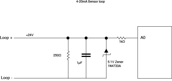
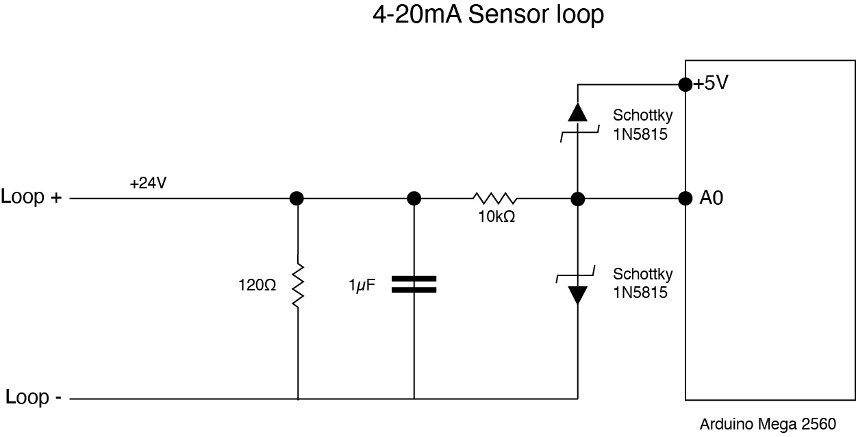
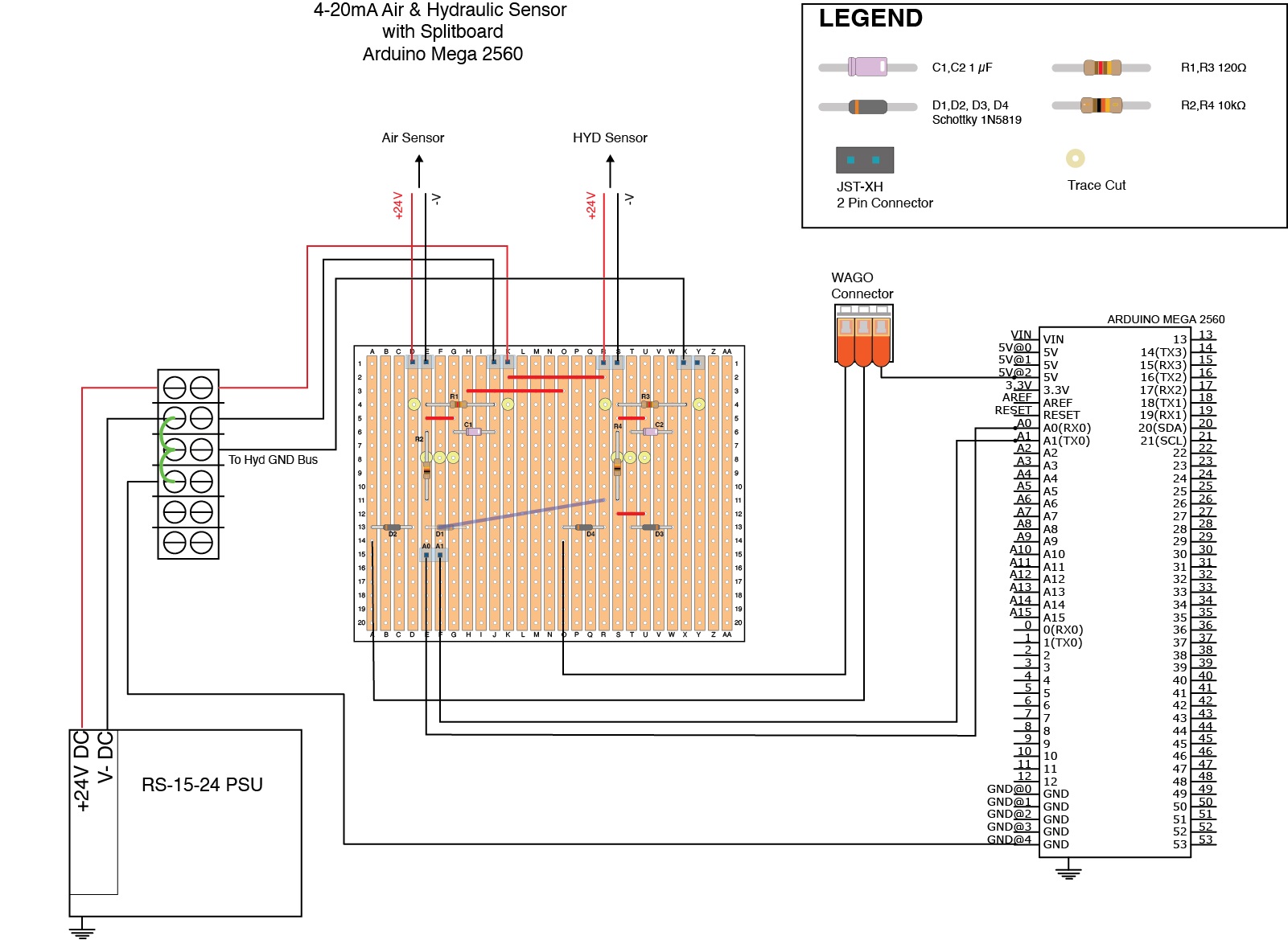
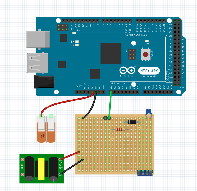
Two images here - overall schematic with splitboard (used DIYLC for this layout), and and loop schematic for a typical circuit I am using. I am not using the analog reference - although after reading through the forum, after I complete the splitboard and become familar with this process, I will go back and update the code and make changes to the circuit.
Air & Hydraulic Sensor with splitboard
As I mentioned, tested on breadboard and the system works well. Given my lack of experience, welcome any advice/criticism on the Splitboard layout before I move to soldering.
Shelley


