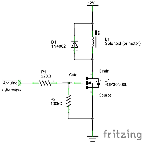
yes I did it is wired exactly like the diagram except the pump is on alligator clips
Alligator clips is (99%) not a problem. What matters way more is the rest of the setup. Tell us what model numbers you got, for the pump, the FET (transistor), power supplies. Why is this important? The hardware are like the base, the foundation for a house. If that fails, the rest of the house will too. The software is the rest of that house. The walls, roof cannot fix an unstable base. Take some time, ask here if you cannot find the info needed, we'll help you.
the transistor is a weimeet transistor but I don't know where to find the model number.
the pump is a DC 12v 5000rpm motor
I got most of the supplies from an elegoo kit, the name is (the most complete starter kit mega 2560 project)
what other information do you need about this project to help me fix my problems?
It should be visible on the transistor, look closely.
Anything more? How many amps it uses?
What power supply or supplies you got? Voltage, Amperage.
You will need a diode to connect in parallel with the motor, but in reverse. I say fly wheel diode, but there are other names:
When something inductive (the motor) is turned off, a voltage spike will occur that can damage, in this case, the transistor. The diode is there to let the spike go back to positive voltage.
What components do you have in the kit?
the things it says on the transistor are 8a28rl and p3ono6le
and would a diode rectifier work?
the things in the kit are the following:
mega 2560controller board
LCD 1602 module (with pin header)
rc522 rfid module
prototype expansion module
power supply module
gy-521 module
servo motor sg90
stepper motor
uln2003 stepper motor driver module
hc-sr501 pir motion sensor module
sound sensor module
water level detection sensor module
ultrasonic sensor
ds1307 rtc module
rotary encoder module
dht11 temperature and humidityy module
ir receiver module
joystick module
romote
max 7219 module
1 digit 7-segment display
l293d
74hc595 ic
active buzzer
passive buzzer
potentiometer 10k
5v relay
fan blade and 3-6v motor
membrane switch module
830 tie-points breadboard
9v battery with snap on connector clip
9v1a adapter
64 breadboard jumper wire
female to male Dupont wire
USB cable
resistor
thermistor
diode rectifier
100uf electrolytic capacitor
10uf electrolytic capacitor
npn transistor pn2222
npn transistor s8050
tilt ball switch button
red led
yellow led
blue led
green led
white led
rgbled
104pf ceramic capicitor
22pf ceramic capisitor
phoresistor(photocell)
An old FET, but it'll do the job. You need a couple of resistors, and this is actually a schematics and components resembling your setup... hm ![]()
Source https://www.g7smy.co.uk/
Sure, you got 4 diodes in a bridge. Can you figure out how to connect it? Only two legs are needed.
About the PSU('s?) and the pump, if you don't know at how many amps they are rated, I guess you just have to take a dice... And never ever run the pump like in your diagram, your Arduino will suffer the consequence.
thank you I think that I finally figured it out.
Great, just the code left! Divide it into simple functions such as sense soil moist, set LEDs, and motor on / off.
got it it works great, thanks!
This topic was automatically closed 180 days after the last reply. New replies are no longer allowed.
