Automatic plant watering system

Hey, I'm an avid Arduino user.
Just going to buy one, and I want my first project to be this, but a really simplified version. I'm going to use a soil Moisture sensor connected to an arduino, which is connected to a relay, which will be connected to a water pump.

So a few questions.
I was told about using a relay by someone with technical experience, I would like to know why is the relay necessary? Why do I need to tell the relay to turn on the motor, why can't I tell the motor to turn on straight away? (eliminating the middle man?)

Secondly, I have no major coding experience, so I was hoping someone could help me. Before I purchase the pump, I want to make sure the sensor coupled with the arduino works perfectly, so I want it to show sensor values on a popup window (maybe using the "serial.printIn" Command?)

So this is the sensor im going to use
http://www.lankatronics.com/soil-dust-humidity-water-moisture-sensor.html
I checked out some stuff online and I saw some codes but they used a grove shield, however I want to connect this without a Grove shield.
So could I get some kind of basic code that reads the sensor value and outputs it to the computer screen. Just as simple as that for now, I want to code the major part of it using the relay and pump myself (or atleast try to), So just need help on the starting point.
Oh, and a little help on how to connect the sensor to the Arduino, which connections to use and whatnot
Will be purchasing the Arduino Uno and the Sensor tomorrow.

Thanks for the help :slight_smile:

Decide what pump you want to use first, and then spec the power supply and circuit from that. The pump will certainly take more current than the Arduino I/O pins can provide directly, so you will need to provide some sort of driver circuit for it. That could be either a motor driver or a relay, but note that you can't drive a relay directly from an Arduino I/I pin either so you would need to use a driver circuit to operate the relay in any case. (Relay shields are available which include the necessary driver circuit.) In this case I suggest you would be better off using a motor driver rather than a relay since this will give you more flexibility to control the pump speed - and direction, in case if you ever decide to use the same hardware for other motorised projects in future.

If the pump you select can be driven with 12V or less and uses less than 1A then you have the option of using the Pololu Baby Orangutan clone, which has an integral dual h-bridge motor driver - it has the advantage of being small and cheap compared to the official Arduino boards, too. The disadvantage is that it's not the right size for the standard Arduino shields, if you wanted to use any of them - but I don't see that you need to, for this project.

PeterH:
Decide what pump you want to use first, and then spec the power supply and circuit from that. The pump will certainly take more current than the Arduino I/O pins can provide directly, so you will need to provide some sort of driver circuit for it. That could be either a motor driver or a relay, but note that you can't drive a relay directly from an Arduino I/I pin either so you would need to use a driver circuit to operate the relay in any case. (Relay shields are available which include the necessary driver circuit.) In this case I suggest you would be better off using a motor driver rather than a relay since this will give you more flexibility to control the pump speed - and direction, in case if you ever decide to use the same hardware for other motorised projects in future.

If the pump you select can be driven with 12V or less and uses less than 1A then you have the option of using the Pololu Baby Orangutan clone, which has an integral dual h-bridge motor driver - it has the advantage of being small and cheap compared to the official Arduino boards, too. The disadvantage is that it's not the right size for the standard Arduino shields, if you wanted to use any of them - but I don't see that you need to, for this project.

Before I start deciding on the motor, I want a simple code that uses the sensor and outputs the value of the moisture, is there anyway you could come up with some sample code? I want this so that i could take apart this code and examine it to help me code myself.
And regarding your post, what exactly is a Driver circuit? From what I get its something that provides a higher current to the pump since the arduino cannot provide this?
A relay cannot be directly connected to an arduino?

From what I can see of the web page you linked to, it just needs Vcc and GND connections to the Arduino, and the analog output connected to an analog pin on the Arduino. The Arduino IDE comes with some example sketches that show how to read an analog input and print the value to the serial port.

The Arduino I/O pins can only handle about 20 mA safely, and typical relays and motors use massively more current than that. You need something to amplify the current from the Arduino. This is often called a driver circuit, and they usually use transistors to control the current.

PeterH:
From what I can see of the web page you linked to, it just needs Vcc and GND connections to the Arduino, and the analog output connected to an analog pin on the Arduino. The Arduino IDE comes with some example sketches that show how to read an analog input and print the value to the serial port.

The Arduino I/O pins can only handle about 20 mA safely, and typical relays and motors use massively more current than that. You need something to amplify the current from the Arduino. This is often called a driver circuit, and they usually use transistors to control the current.

I see, Thanks, Alot of the information you gave to me is pretty enw and I appreciate all the gained knowledge :smiley:

Anyway before i set off to connect the pump and motor drivers and everything else, I want to basically connect the sensor to the arduino and get the sensor readings.

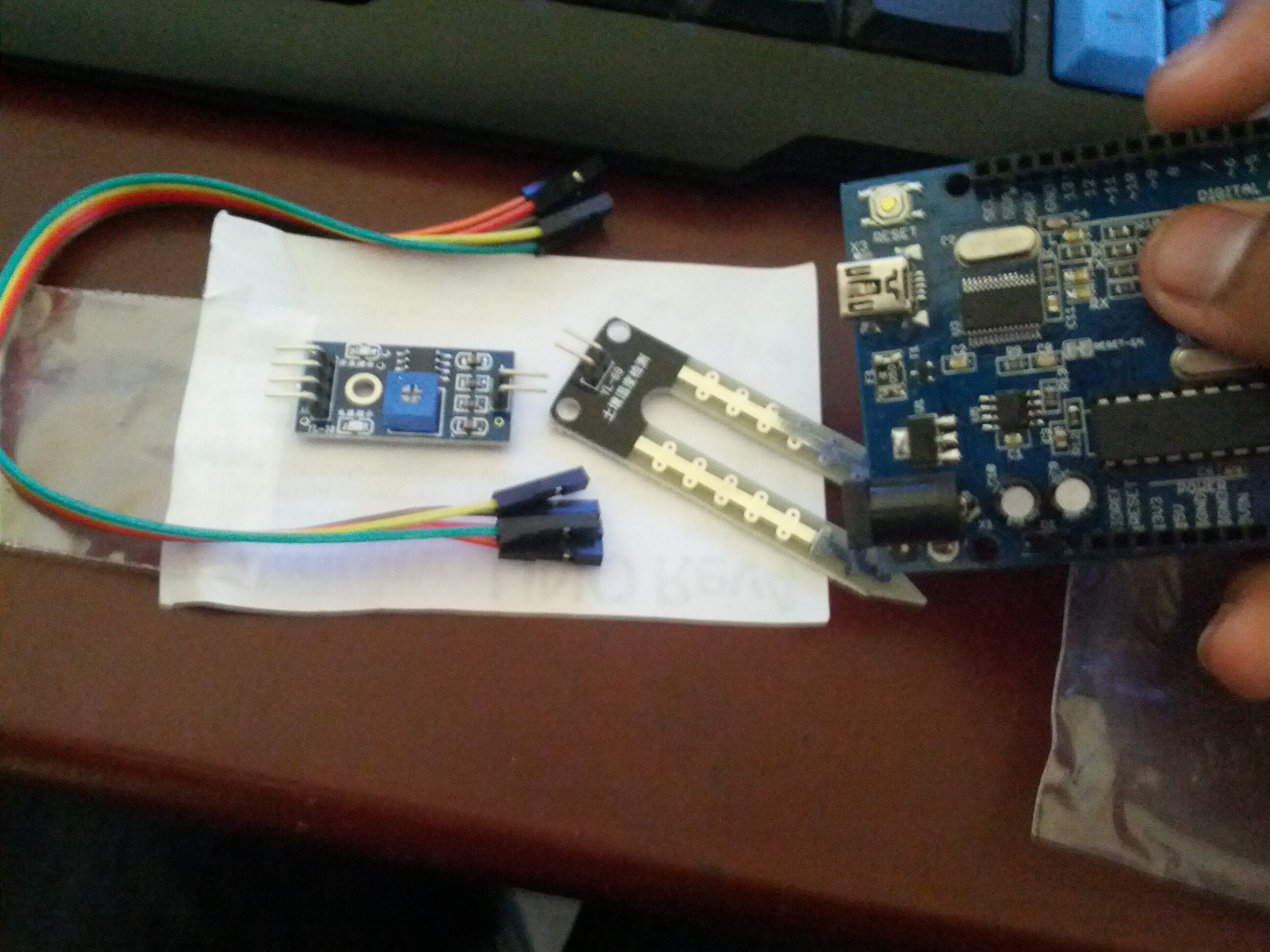
I bought the arduino and the sensor, they are pictured below

How would I go about connecting the sensor to the arduino? I'd require only the analog input and not the digital
I realise the two connectors on the LM 393 should be connected to the two connectors on the sensor
And the four on the other side of the LM393 should go to 1. Power supply (5V connector on the arduino) 2. Ground (GND on the arduino) And one for the analog output (A0 On the arduino)
It's just that I dont know how to connect it... Do I use the given set of four to four connectors to connect the Sensor to the LM 393 or four the LM 393 to the arduino? And if so what do I use to connect the rest?

Bump :slight_smile:

Are you asking what the circuit design should be, or the practicality of how you make an electrical connection between a terminal on the Arduino and a terminal on your sensor board?

PeterH:
Are you asking what the circuit design should be, or the practicality of how you make an electrical connection between a terminal on the Arduino and a terminal on your sensor board?

Probably the practicality
While I was waiting, I did some research of my own, and I think the wires given with the sensor are called Dupont Wires, and they are Female-Female, and there are five of them. So this would work for connecting the sensor terminal to the LM393 chip terminal.
Now connecting the LM393 chip to the arduino is a different case, I'm guessing the Arduino requires a male cable? So would I have to buy a female to male wire? and then connect the female side to the chip and sensor combination, and the male to the arduino? (Buy one each for VCC, GND and A0)

Again this is all assumption based on what I've read online and read on different sensor manuals.
Thanks for the help and Interest again :slight_smile: Appreciate it (Y)

Your UNO has female headers. You have some female jumper wires. To connect these together you need some male-to-male jumper wires, which might be properly made for the purpose or just some solid core wire with the ends stripped. This sort of thing is commonly available in electronic hobby shops. If you don't have access to anything like that, you can just use the snipped-off end of a sewing pin, or a strand taken out of a heavier wire, or anything else that is physically the right size and conductive which you can push into the terminals. If you're looking for a better long term solution, it's possible to get the crimp terminals and housing blocks separately so you could replace the female terminal on one end of those wires with a male terminal, or make up your own connector cable from scratch. Putting all the terminals in a single housing gives much better mechanical support to the connector than using a separate shroud for each terminal, as you have currently.

PeterH:
Your UNO has female headers. You have some female jumper wires. To connect these together you need some male-to-male jumper wires, which might be properly made for the purpose or just some solid core wire with the ends stripped. This sort of thing is commonly available in electronic hobby shops. If you don't have access to anything like that, you can just use the snipped-off end of a sewing pin, or a strand taken out of a heavier wire, or anything else that is physically the right size and conductive which you can push into the terminals. If you're looking for a better long term solution, it's possible to get the crimp terminals and housing blocks separately so you could replace the female terminal on one end of those wires with a male terminal, or make up your own connector cable from scratch. Putting all the terminals in a single housing gives much better mechanical support to the connector than using a separate shroud for each terminal, as you have currently.

Will be getting some male to male connectors then.
Currently all the female jumper wires and glued together, however they are easily removed, it is safe to remove them so i can use two for the sensor and the other three for teh VCC, GND and A0, Right?
I dont get the part about crimp terminals, are you talking about making a housing for the whole project? If so I don't think that is necessary at the moment.
What do you mean by a seperate shroud for each terminal? You mean im using one wire per terminal?
Anyway will be buying make to male connectors, Or would it be simpler to use a female to male connector to connect the LM393 chip to the Arduino? You know, instead of a female to female to male to male, I could just use the female to male

Here is a picture showing a housing for three terminals, and some female crimp terminals:

http://www.ebay.co.uk/itm/2-x-3-Pin-PC-Header-plug-connector-LED-crimps-2-54mm-/140517326027?pt=UK_Computing_Case_Mods_Stickers_Decals&hash=item20b77c3ccb

If you remove the black plastic piece from the end of the leads you already have, you'll see this is basically what they are. The black housings are available in various sizes from one up to a dozen or so terminals. As well as the female terminals shown there, you can get similar male terminals. Both sorts just crimp onto the end of a wire.

Given that you already have some individual housings, gluing them together is perfectly OK to make a bigger housing.

If you decide to buy any more terminals and/or housings, you should know that they're bog standard 0.1" pitch connectors and you should plan to buy a bag of a hundred or so for a few pence each. Buying then individually as advertised in that link is extraordinarily expensive.

In the short term, buying male-to-male jumper wires, or just finding a bit of metal to join the two female connectors together is a perfectly reasonable way to complete your circuit for testing.

PeterH:
Here is a picture showing a housing for three terminals, and some female crimp terminals:

http://www.ebay.co.uk/itm/2-x-3-Pin-PC-Header-plug-connector-LED-crimps-2-54mm-/140517326027?pt=UK_Computing_Case_Mods_Stickers_Decals&hash=item20b77c3ccb

If you remove the black plastic piece from the end of the leads you already have, you'll see this is basically what they are. The black housings are available in various sizes from one up to a dozen or so terminals. As well as the female terminals shown there, you can get similar male terminals. Both sorts just crimp onto the end of a wire.

Given that you already have some individual housings, gluing them together is perfectly OK to make a bigger housing.

If you decide to buy any more terminals and/or housings, you should know that they're bog standard 0.1" pitch connectors and you should plan to buy a bag of a hundred or so for a few pence each. Buying then individually as advertised in that link is extraordinarily expensive.

In the short term, buying male-to-male jumper wires, or just finding a bit of metal to join the two female connectors together is a perfectly reasonable way to complete your circuit for testing.

Connected it using wires I found from random wire in my house, and I'm glad to say it works :slight_smile:
Managed to get it to output values like this

That is being not in water at all, then slightly submerged and then completely submerged. :slight_smile:
Now to move on to the next step.
Getting it to turn on a pump when certain values are reached.
First off, I have a normal aquarium pump that I dont use anymore, can this be used for this project? It's a normal one that connects to a socket at home to operate.
Also for other parts (as you said to Amplify the current) What would I need? Could you please link me to the items from this website as they are the best hobby-ist shop in my area.
http://www.lankatronics.com/
Anything else would take too long to get from.
Thanks alot for the help thus far, You've really helped me see alot of progress :slight_smile:

Kando:
First off, I have a normal aquarium pump that I dont use anymore, can this be used for this project? It's a normal one that connects to a socket at home to operate.

That sounds like a mains voltage pump, which is not convenient to control with an Arduino. You really want a low voltage DC pump - mine came from ebay for a few quid and there are plenty of similar ones advertised. Once you have selected the pump you will need to provide a power supply for it, and a driver circuit. The driver can either be integral to the Arduino board, or a shield that fits onto the Arduino (if you use an official board or compatible), or a separate board connected by wires. In my case I used a Pololu Baby Orangutan which has an integral h-bridge motor driver, which worked out a lot smaller and cheaper than using an official Arduino and separate driver board.

PeterH:

Kando:
First off, I have a normal aquarium pump that I dont use anymore, can this be used for this project? It's a normal one that connects to a socket at home to operate.

That sounds like a mains voltage pump, which is not convenient to control with an Arduino. You really want a low voltage DC pump - mine came from ebay for a few quid and there are plenty of similar ones advertised. Once you have selected the pump you will need to provide a power supply for it, and a driver circuit. The driver can either be integral to the Arduino board, or a shield that fits onto the Arduino (if you use an official board or compatible), or a separate board connected by wires. In my case I used a Pololu Baby Orangutan which has an integral h-bridge motor driver, which worked out a lot smaller and cheaper than using an official Arduino and separate driver board.

The problem is im running on a tight schedule :confused:
What would it take to connect a mains voltage pump to an arduino?
Also what about this? It's a bit on the expensive side, but im not too sure
http://www.lankatronics.com/12v-60w-high-pressure-micro-diaphragm-water-pump-automatic-switch-5l-min.html
What about this? can this be used to control the water flow?
http://www.lankatronics.com/solenoid-hcne1-0520-12v.html
Looking for options on something that I can code on (as a total beginner) and something that wont take too long, Got around 2 weeks to provide a final prototype
What other options do I have to automatically water the plant based on the sensor readings? Could you please (If it's not too much trouble) Look through that site and get me some component that I could use from there? :slight_smile:

That looks like a massive pump - what sort of water flow rate and pressure do you need to achieve? You could use that pump, but it's going to need a pretty chunky motor driver circuit and power supply. For a domestic plant waterer supplying a few CC at a time I was envisaging something like a 1W pump, not 60W.

The second link you posted is to a solenoid operated valve. I don't understand how that would be used in your project. All I'd envisage you needing would be a DC pump, power supply, driver circuit for the pump (which might be integral with the Arduino or a separate board), and the moisture sensor.

What about this? can this be used to control the water flow?
Lankatronics is under construction

Yes it can, but only if you have water under pressure which I assume you don't or we wouldn't be talking about pumps.

What would it take to connect a mains voltage pump to an arduino?

A mechanical or solid-state relay would be the simplest I think.

That 60W pump is probably over kill unless you have a lot of plants to water.

I would just get a relay shield, depending on its rating it will control just about any motor you are likely to need.

So could I get some kind of basic code that reads the sensor value and outputs it to the computer screen. Just as simple as that for now,

Serial.println (analogRead(sensor_input_pin));

Rob

PeterH:
That looks like a massive pump - what sort of water flow rate and pressure do you need to achieve? You could use that pump, but it's going to need a pretty chunky motor driver circuit and power supply. For a domestic plant waterer supplying a few CC at a time I was envisaging something like a 1W pump, not 60W.

The second link you posted is to a solenoid operated valve. I don't understand how that would be used in your project. All I'd envisage you needing would be a DC pump, power supply, driver circuit for the pump (which might be integral with the Arduino or a separate board), and the moisture sensor.

Yes I too think the pump is overkill, But from what I've seen that seems to be my only option, It is also too expensive however... Would using the mains voltage pump be too much work for a beginner?
Cant I use the solenoid valve to stop/Allow the water flow? For example if I put a water source on top and the valve at the bottom, water will be flowing down due to gravity, and therefore I can control it with the valve connected to the arduino?

Graynomad:

What about this? can this be used to control the water flow?
Lankatronics is under construction

Yes it can, but only if you have water under pressure which I assume you don't or we wouldn't be talking about pumps.

What would it take to connect a mains voltage pump to an arduino?

A mechanical or solid-state relay would be the simplest I think.

That 60W pump is probably over kill unless you have a lot of plants to water.

I would just get a relay shield, depending on its rating it will control just about any motor you are likely to need.

So could I get some kind of basic code that reads the sensor value and outputs it to the computer screen. Just as simple as that for now,

Serial.println (analogRead(sensor_input_pin));

Rob

For the first part, I dont mind using water under pressure, I thought pumps would be the easiest option thats why we were talking about them... However I don't think I'm able to find an appropriate pump than normal mains voltage aquarium ones.

So it is possible to connect the mains voltage pump to the arduino and have the arduino control it? Looking at it atm that seems to be the easiest option for me (I say this because I don't know how hard it is to setup).. Any Idea on how that would be done and whehter it's too much for a beginner to handle?

Yup I got that part, I wrote a bit of code that Outputs a sentence depending on the water level, For example "Too much water" if there is too much water and "Need more water" if there is less water etc..
Now all I need is a way to control water flow to the plant, I dont mind it being a Pump, a solenoid, Or ANY other method you can think of
Again, this is the hobby site where I live with most of the stuff :slight_smile:
http://www.lankatronics.com

Thanks again :slight_smile:

You seem to be considering going to great lengths to design your solution using parts from a single supplier who has an extremely limited range and nothing really suitable. Is there really no access to alternative suppliers? Here in the UK I had no trouble sourcing a cheap DC pump, Arduino clone and wall wart power supply and the parts only cost a few quid each and arrived within days. If somebody has a gun to your head you could make something work using that mains powered pump and a solenoid valve and a motor/relay driver to operate the solenoid, but it would be a very awkward solution - I don't understand the constraints which would oblige you to take that approach.

PeterH:
You seem to be considering going to great lengths to design your solution using parts from a single supplier who has an extremely limited range and nothing really suitable. Is there really no access to alternative suppliers? Here in the UK I had no trouble sourcing a cheap DC pump, Arduino clone and wall wart power supply and the parts only cost a few quid each and arrived within days. If somebody has a gun to your head you could make something work using that mains powered pump and a solenoid valve and a motor/relay driver to operate the solenoid, but it would be a very awkward solution - I don't understand the constraints which would oblige you to take that approach.

Haha, I Live In Sri Lanka :stuck_out_tongue:
Very Small country, not many hobby/enthusiast electronic shops around here
That site and this one are the only ones I could find
http://www.lkbotics.com/index.php?route=common/home

Sad Reality of living in a third world country :confused:

There are a lot of ways to make things without buying special devices.

For the pump, you could use a tank that collects rain water, located above the plants.
Then release the water onto the plants.

You can use a water pump from a windshield motor
A water pump from a fish tank
You can open a valve and allow water to drain
You can use a stepper to push on a hose to block off the hose, or back off and allow water to drain.

You can use a tipping rain gauge of your own make to measure water and control quantity.

If you have a simple motor, you can make a water wheel to get water from a stream up to your plant.

If you have a hill with a steep drop, you can use mechanical water pump to pump water up higher or to a different location.

There is no reason in the world to avoid using a mains powered pump if that is what you have.

If you have a DC motor and some special plastic tubing, you can make a peristaltic pump.

If you have a large pump and a large tank, you can fill the tank once a week (or when low) and then drain out water to your plants.

Sometimes we loose sight of the simple things when we have easy access to special items.