I recently purchased a brushless peristaltic pump and have a question about it, which I'm hoping someone on this forum can answer. As you can see from the attached image, the pump has 5 wires. I've already figured out how to send a PWM signal and change the flow direction of the pump using an Arduino UNO, but the wire I am specifically enquiring about in this post is the green one, or the feedback signal. I am trying to control the peristaltic pump with a PID controller, and from what I understand, I need a measured process variable to help the controller determine how to minimize error, which I'm assuming the feedback signal can provide me with. 1.) How exactly would I go about reading/interpreting the signal from the green wire using an Arduino UNO? Is there a standard protocol to follow when attempting to read the feedback signal of a brushless motor? 2.) I'm aware that I need to know the pulses per revolution of the motor, which I already know, in order to calculate the RPM, but what equation should I be using after I've figured out how to interpret the feedback signal from the green wire?
You need to identify what type of signal the green wire is carrying. It's likely an encoder or tachometer signal.
If it's an encoder signal, you could use an interrupt-based method to count the number of pulses generated by the encoder. This will help you track the actual revolutions of the motor.
If it's a tachometer signal you could use the pulseIn() function to measure the pulse duration, which will also give you information about the motor speed.
never use pulseIn() its a blocking function and will prevent you from doing anything else. use an interrupt along with a timer to measure the time it takes for a full revolution
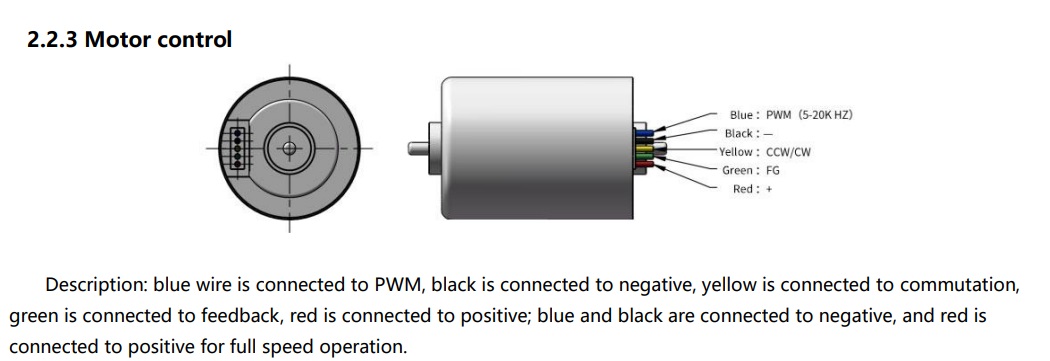
The specs of the motor is in section 2.2, but it does not state whether the feedback wire is a tachometer or encoder signal. I guess I could try both methods to determine what signal it is.
So I should use your suggestion of using an interrupt based method to count the number of pulses? I'm assuming I need to attach the green wire to one of the interrupt pins on the Arduino board right? so for the UNO that would be either pin 2 or 3?
const byte feedbackPin = 2;     // green wire
const byte directionPin = 4;    // yellow wire
const byte speedPin = 5;        // blue wire (needs to be a PWM pin. on UNO pins 3,9,10,11 are at 490,20 Hz and pin 5 and 6 are at 976,56 Hz. Required 5-20KHz => 5 or 6 better suited)

int currentPWMSpeed = 0;

void setup() {
  pinMode(feedbackPin, INPUT);
  pinMode(directionPin, OUTPUT);
  pinMode(speedPin, OUTPUT);

  analogWrite(speedPin, currentPWMSpeed);
  digitalWrite(directionPin, LOW);

  Serial.begin(115200);
  Serial.println(F("FEEDBACK"));
}

void loop() {
  int command = Serial.read(); // will return -1 if nothing to read
  switch (toupper(command)) {

    // set speed 0 = stop, 9 = full speed, 1..8 linear interpolation in between
    case '0' ... '9':
      currentPWMSpeed = map(command, '0', '9', 0, 255);
      analogWrite(speedPin, currentPWMSpeed);
      // Serial.print(F("PWM set to ")); Serial.println(currentPWMSpeed); // if you don't use the Serial plotter
      break;

    // stop
    case 'S':
      analogWrite(speedPin, 0);
      // Serial.println(F("STOP")); // if you don't use the Serial plotter
      break;

    // full speed
    case 'F':
      analogWrite(speedPin, 255);
      // Serial.println(F("FULL SPEED")); // if you don't use the Serial plotter
      break;

    // ignore anything else
    default:
      break;
  }

  Serial.println(digitalRead(feedbackPin) == LOW ? 0 : 100); // for the Serial plotter
}
you wire the power to the motor (don't power from your arduino), join grounds.
connect the green wire to pin 2
connect the yellow wire to pin 4
connect the blue wire to pin 5
Then upload open the code and open the Serial plotter (in the tools) at 115200 bauds
you can type a number from 0 to 9 and enter to set the speed or S for stop or F for full speed.
the plotter will be like a cheap oscilloscope showing what's going on (at the speed of the loop) with the green wire output.
Above is a segment of what the plot looks like. From a layman's interpretation it looks like a pulse of some sort. Does this mean that it is an encoder signal?
yes it seems you get a pulse from time to time. it's not regular - did you modify the speed when capturing the snapshot ? (at constant speed if this is indeed one pulse per rotation you should get spikes at regular intervals unless the spike is so short that the polling method does not work and then we need to go to ISR)
it's not very convincing... either there is bouncing happening or it's not a pulse signal but a PWM.
let's try a different code counting the number of RISING (LOW to HIGH) transitions on that pin and reporting it every 5s
const byte feedbackPin = 2;     // green wire
const byte directionPin = 4;    // yellow wire
const byte speedPin = 5;        // blue wire (needs to be a PWM pin. on UNO pins 3,9,10,11 are at 490,20 Hz and pin 5 and 6 are at 976,56 Hz. Required 5-20KHz => 5 or 6 better suited)

int currentPWMSpeed = 0;
volatile unsigned long pulseCount = 0;
unsigned long startTime;
unsigned long samplingDuration = 5000;  // 5 seconds in milliseconds

void countPulse() {
  pulseCount++;
}

void setup() {
  pinMode(feedbackPin, INPUT);
  pinMode(directionPin, OUTPUT);
  pinMode(speedPin, OUTPUT);
  analogWrite(speedPin, currentPWMSpeed);
  digitalWrite(directionPin, LOW);
  Serial.begin(115200);
  attachInterrupt(digitalPinToInterrupt(feedbackPin), countPulse, RISING);
}

void loop() {
  int command = Serial.read(); // will return -1 if nothing to read
  switch (toupper(command)) {

    // set speed 0 = stop, 9 = full speed, 1..8 linear interpolation in between
    case '0' ... '9':
      currentPWMSpeed = map(command, '0', '9', 0, 255);
      analogWrite(speedPin, currentPWMSpeed);
      break;

    // stop
    case 'S':
      analogWrite(speedPin, 0);
      break;

    // full speed
    case 'F':
      analogWrite(speedPin, 255);
      break;

    // ignore anything else
    default:
      break;
  }


  if (millis() - startTime >= samplingDuration) {
    // --- critical section, we simply detach the ISR to keep things simple ---
    detachInterrupt(digitalPinToInterrupt(feedbackPin));
    unsigned long pulseCountCopy = pulseCount;
    pulseCount = 0;
    attachInterrupt(digitalPinToInterrupt(feedbackPin), countPulse, RISING);
    // --- end of critical section
    Serial.print("Pulse count: "); Serial.println(pulseCountCopy);
    startTime = millis();
  }

}
run that with the Serial monitor (not the plotter) opened at 115200 bauds
it should report the number of pulses seen every 5s and this should be consistent
try to increase the speed to 1, 2, 3, 4, ... and see if there is a change in the pulse count
copy and paste the Serial monitor output (as text, with code tags) here
I should note that after running the code and changing the PWM, the pulse count takes a while to stabilize (about 30 seconds to a minute). Also, I'm not sure if it's a characteristic of the motor, but the PWM level is reversed, so a PWM level of 1 is full speed and a PWM level of 9 is zero speed.
The following is the first 50 seconds of pulse count after the readings have somewhat stabilized: