Hi, I am using a 2 meter strip with 144 led/m on a WS2812B led strip. By doing the maths on how much current would be required to power this we get
60mA * 288 = 17.28 amps.
However, I am not planning on having the LED's at full brightness and I do not plan on having any white LED that will draw more current. I will have the LED's at 40% brightness so I would need ~7a. But once again this would be if the LED was white.
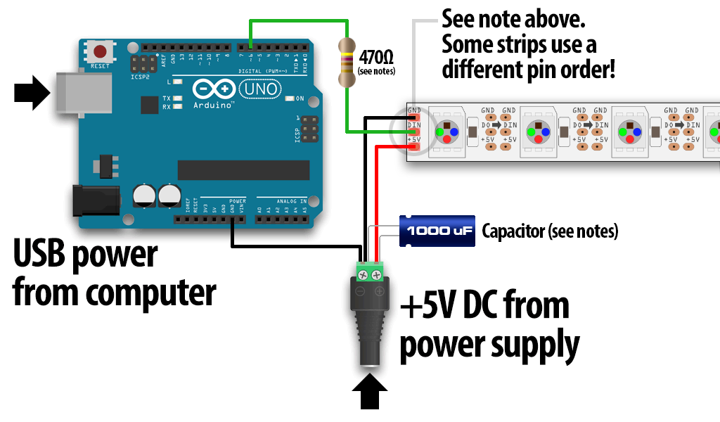
So with these numbers, I bought a 5v 10a power supply. The schematic that I am using is attached to this post. It is from the NeoPixels uberguide, in the section "Powering NeoPixels". I have also attached a picture of the connections that were already wired up on the LED's.
I am completely new to any sort of circuitry especially at these high currents and to be honest it scares the crap out of me worrying that I will completely burn down my house!
So here are my questions:
I am currently using the Arduino Uno starter kit along with the included jumper wires. From looking up online I can see that the gauge of these wires is 22 AWG which I believe is not suitable for the ~7a that I need (Please correct me if I am wrong). So I know I would need to get better wires, however I am not sure what gauge wires I would need?
If I was to get different wires, for example 16 or 14 AWG, are they available as jumper cables and will they fit into the Arduino pins?
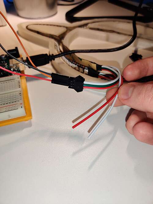
My LED strips have 5 wires coming off of them already, two red, two white, and a data cable. One of each of the white and red cables a long with the data cable, go to a female connector that I plug the jumper cables into. Would I be able to plug the bigger cables into this connector and are these wires suitable to handle the current or do I need to unsolder them and re solder new wires?
I also bought a barrel jack adapter that splits the power supply into the + and - connections. I believe it is called a 5.5mm x 2.1mm adapter. The brand is EFISH and once again I am wondering if this can handle the current?
As you can see from the schematic, there is a 1000uF capacitor on the + and - from the power supply, I then connect the wires to the LED as well as the ground to the Arduino. What is the best and safest way to cover all of this once I am done testing and ready to install?
Finally, I know that it is suggested to power both ends of a strip to ensure equal brightness and colour accuracy especially across 2m of LEDs. The end of my strip has the same wires already connected however, instead of the female connector, it has a male connector. How do I power this end of the strip? Do I simply wire the white and red cables into the same power supply as I did with the other end?
I know there are a lot of questions here but I am very excited to get this working but mainly I am very nervous about all of it! So any help or input would be greatly appreciated!
The wiring looks good. The "fat" cables are the + and - between that 5 volt plug and the LED strip.
I don't know the AWG standard. Important is to know the length of those cables.
I suggest for short ( a few meters ) cables 1.5 square mm, longer cables 2.5 or even 4.0 square millimeter cables for longer then 20 meters.
Do I simply wire the white and red cables into the same power supply as I did with the other end?
Yes.
The library to drive these chips have a brightness control, set them only once in the setup function to limit the current to a safe value to protect your power supply.
The actual detail of what happens when you draw too much current from a supply depends on the design of the power supply. The options are, it gets very hot and the voltage drops. The power supply cuts out or it hiccups, that is it shuts down because of too much current, then because there is no current it starts up again. This repeats continuously.
Grumpy_Mike:
The actual detail of what happens when you draw too much current from a supply depends on the design of the power supply. The power supply cuts out or it hiccups, that is it shuts down because of too much current, then because there is no current it starts up again. This repeats continuously.
The term for that is called "Fold back" in the product description.
Railroader:
The wiring looks good. The "fat" cables are the + and - between that 5 volt plug and the LED strip.
I don't know the AWG standard. Important is to know the length of those cables.
I suggest for short ( a few meters ) cables 1.5 square mm, longer cables 2.5 or even 4.0 square millimeter cables for longer then 20 meters.
The cable from the power supply to the start of the LED strip will be about a meter. Should I desolder the current wires with wires that are 1.5 square mm to make sure I have no issues?
The library to drive these chips have a brightness control, set them only once in the setup function to limit the current to a safe value to protect your power supply.
The actual detail of what happens when you draw too much current from a supply depends on the design of the power supply. The options are, it gets very hot and the voltage drops. The power supply cuts out or it hiccups, that is it shuts down because of too much current, then because there is no current it starts up again. This repeats continuously.
Thanks for your response Yeah currently I have the brightness set really low in my script. How do I make sure the cables and the adapter for the power supply jack can withstand the current? And what would the scenario look like if they can't?
Sorry if these questions are trivial I just want to make sure I'm not doing anything stupid
No, wait a little. Run Your project and sense the temperature of the cables using You fingers. If they feel more warm than "lightly", more then body temperature You can consider un updimensioning of the cables.
You can also use a DVM and measure between +pwr plug and + LED strip. Hard to give any voltage limit but it should be kept small, less than 100 mV, as "between thumb and finger".
owjo:
Thanks for your response Yeah currently I have the brightness set really low in my script. How do I make sure the cables and the adapter for the power supply jack can withstand the current? And what would the scenario look like if they can't?
Sorry if these questions are trivial I just want to make sure I'm not doing anything stupid
Tune up the power and use Your fingers as temperature sensors. Staying below body temperature in the cables during the test is okey in my opinion.
Railroader:
No, wait a little. Run Your project and sense the temperature of the cables using You fingers. If they feel more warm than "lightly", more then body temperature You can consider un updimensioning of the cables.
You can also use a DVM and measure between +pwr plug and + LED strip. Hard to give any voltage limit but it should be kept small, less than 100 mV, as "between thumb and finger".
So I measure between the +pwr and the + at the start of the LED strip or the end? Also as I will be having the capacitor, the two - wires and the two + wires (from both ends of the led) coming out of the adapter from the power supply, how should I cover these wires once I am finished testing?
Capacitors and wires? I don't think I understand properly. Decoupling capacitors needs to be as close to the object, pwr supply or load, as possible. Write a figure on paper?
Railroader:
Capacitors and wires? I don't think I understand properly. Decoupling capacitors needs to be as close to the object, pwr supply or load, as possible. Write a figure on paper?
Sure, I'll try show what I'm talking about, I'm definitely not using the correct terms
Here are two images from a tutorial on how to connect the WS2812B LED's. In the images, the person has placed the capacitor into the adapter with the wires also coming out of it. If you have a look at the original schematic this is also shown. So I was wondering what the best way to tidy this up would be?
However, I am not planning on having the LED's at full brightness and I do not plan on having any white LED that will draw more current. I will have the LED's at 40% brightness so I would need ~7a. But once again this would be if the LED was white.
You'll probably be OK but PWMswitches between zero and 100% . if a color is on at all (even very dim), each color is running ~20mA for at-least a short period of time. So for most color/brightness combinations you'll be hitting 17A for some percentage of the time, even if you're only averaging 7A.
DVDdoug:
You'll probably be OK but PWMswitches between zero and 100% . if a color is on at all (even very dim), each color is running ~20mA for at-least a short period of time. So for most color/brightness combinations you'll be hitting 17A for some percentage of the time, even if you're only averaging 7A.
Boosting a cable during the active pulse having an acceptable average ought to be okey but dimensioning the system for worst case is of course the best.
Watching the cables sweat is not good.
DVDdoug:
You'll probably be OK but PWMswitches between zero and 100% . if a color is on at all (even very dim), each color is running ~20mA for at-least a short period of time. So for most color/brightness combinations you'll be hitting 17A for some percentage of the time, even if you're only averaging 7A.
Could this be very dangerous if I don't have the hardware to handle 17A? Also what would happen in this scenario if I only have a 10A supply, will it only go to a max of 10A?
Having a 10 Amp supply the supply likely shuts off, tries to turn on after some delay. No risc in that.
BUT! Check up the power supply manual, how it handles overloads. If it continues delivering 10 Amps things could get uggly.