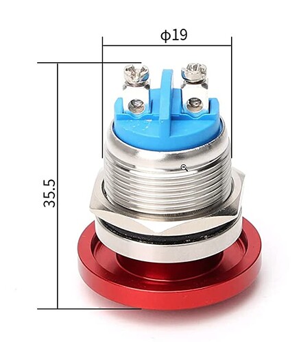
I am trying to wire up several momentary switches - but these only have two poles:
I have one pole going to the PIN5 (digital input) on the arduino, and the other going to the +5V line.
Where do I wire ground to with the 10K pulldown resistor? I was able to make this work with a tactile push button but that had 4 legs, so I am unsure what to do here. I am not an electrical engineer by any stretch of the imagination - so pardon my ignorance.
Thanks!
Wire it to ground and use the internal pull-up resistor.
pinMode(5, INPUT_PULLUP);
1 Like
The internal pullup was giving me unpredictable results, is there a way to do it with the pulldown?
On that tactile switch, that is effectively still a two pole switch right? It just has two pins for each pole
barrychapman:
unpredictable results
That is probably because of bouncing. Have you tried to use a button library?
https://www.arduino.cc/reference/en/libraries/ebutton/
I am pretty new to the arduino stuff - i am not using a button library that i know of
Adapted from the link in post #4:
#include "Arduino.h"
// 1. Include the library
#include "EButton.h"

// 2. Instantiate the object and attach it to PIN 5
EButton button(5);

// 3. Handler method for a single-click
void singleClick(EButton &btn) {
	Serial.println("We have a single-click!");
}

void setup() {
	Serial.begin(115200);
// 4. Attach the handler
	button.attachSingleClick(singleClick);
	Serial.println("\nClick or double-click!");
}

void loop() {
// 5. Tick the object in a loop
	button.tick();
}
I think this will answer most of your questions about connecting buttons of all kinds:
Intended audience
This tutorial is intended for people who have mastered the basics of electronics and C/C++ programming. If you are a beginner and find the concepts difficult, please review the basic examples in the Arduino IDE.
In this tutorial BUTTON will be a generic term for any kind of switch or other input device with mechanical contacts.
Introduction
A common requirement in many projects is to have push buttons, switches or other electro-mechanical devices connected as inputs to an A…
To be clear, it applies to what you have, not just the tactile buttons I've used to illustrate things.
LarryD
January 8, 2023, 7:24pm
8
Wire switches as S3 is wired below.
A LOW on the input pin indicates the switch is closed.
Can you explain more about what you were experiencing with INPUT_PULLUP? What code were you running?
Maybe those switches do not make good contact a very low current flow, not dry circuit type, but are designed for switching higher currents.
Thank you, this clarifies things a lot
If using INPUT_PULLUP, then use this wiring configuration:
Terminal 1 to Pin 5
Terminal 2 to GND 'pinMode(5, INPUT_PULLUP); in the setup() function.
If not, use this wiring configuration:
Terminal 1 to Pin 5
10K pulldown resistor from Terminal 1 to GND
Terminal 2 to +5V
Reffer to @LarryD 's chart
b707
January 9, 2023, 2:26pm
13
barrychapman:
have one pole going to the PIN5 (digital input) on the arduino, and the other going to the +5V line.
Where do I wire ground to with the 10K pulldown resistor?
To the same pole as arduino PIN5.
system
July 8, 2023, 2:27pm
14
This topic was automatically closed 180 days after the last reply. New replies are no longer allowed.

