Hello
How much negative voltage can the Arduino Due analog pin withstand without failure?
During the operation of the prepared system, a negative voltage is also applied to the analog leg but I don't know where the limit is which it can no longer tolerate.
Please also submit your website. I could not find any information on this.
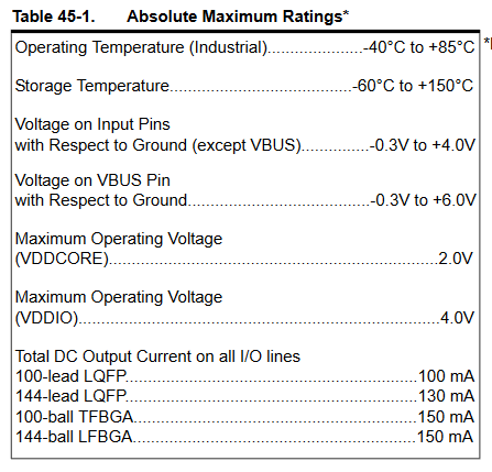
Look into the datasheet under 'maximum ratings' ( chapter 45.1 )
This applies to all inputs - so also to analog inputs.
The datasheet is linked on the arduino site of the Due.
The analogue pins are input pins. Why don't you believe the data sheet? If no distinction is made here between digital and analogue input, than there is no difference in the maximum values.
I don't understand what you mean. Obviously you have very little experience with reading datasheets. Maximum values are maximum values. Dot. The manufaturer knows about them. Everything what extends the maximum values may damage the circuit - no matter what 'states' there may be. That's why they should never be reached in normal operation.
Read the additional Information in the datasheet to 'Maximum Ratings':
Stresses beyond those listed under “Absolute Maximum Ratings” may cause permanent damage to the device. This is a stress rating only and functional operation of the device at these or other conditions beyond those indi- cated in the operational sections of this specification is not implied. Exposure to absolute maximum rating conditions for extended periods may affect device reliability.
As an engineer I would contend that the circuit is not ready at all. It's defective if not staying within datasheet / documented Absolute Maximum Ratings. It can work for some time and you can see this as "good enough", but it's a hidden builtin defect and in the industry or consumer electronics market, your responsibility would be clearly exposed, especially since you knew the pins might get exposed to voltage exceeding Absolute Maximum Ratings.
➜ I'd recommend to face the music and go back to the drawing board
J-M-L
Thanks. But this is not a product. You don't have to worry.
MicroBahner
I am writing a completely imagined example. Suppose there is too much voltage on the mandrel.
Suppose the spike goes onto a multiplexer and then from there to the ADC. The ADC can withstand a maximum of 5V. But when we do not read the value of the ADC, the output of the multiplexer does not have the value of that pin. And the multiplexer can withstand more than 5V. In this case, the pin will not fail until we read more than 5V with it. But if you don't read the value, it can have a voltage higher than 5V.
The lower limit is ~0.3 volts. One way you can protect the input it to put a resistor in series with the input.
I would suggest a 5k resistor then a 0.1µF to ground right near the pin.
The 5K will limit the current so you can go approximately 5v below ground and not have enough current to damage your DUE.
The 0.1µF capacitor has nothing to do with negative voltage but will make your analog readings less likely to pickup noise, giving your better readings.
Then you can imagine it's OK! Or you can imagine you've fried your imaginary Arduino!
You can also imagine that it reads zero with negative voltages and that's actually true as long as you don't fry the thing.
There are internal "protection diodes" in the chip to protect against voltages higher than 5V, or negative voltages. But somewhere I read they are only rated for 1mA so it's easy to fry those and once they fry the whole chip could go...
Here are some protection circuits. Note that they ALL have current limiting resistors. This protects the diodes as well as whatever is connected from excess current, if the resistor is chosen properly. In many cases the 100-Ohm resistor is too low for whatever is connected.
If you use Schottky diodes they will "turn on" at al lower voltage, before the internal diodes start conducting, so the internal diodes are protected.