haven't followed the thread but my understanding of the primary/original need for the I term is that if you were driving a DC motor, the error (P) is the output to the motor. but as the error becomes zero, there's no longer any output to the motor.
so the i-term is used to build up a value that drives the motor when the error becomes zero.
it's not obvious how it should be used in a digital system. some have suggested it can be used to overdrive a motor to increase the drive force which is not proportional to the P term
so if the acceleration is zero, your maintaining the velocity which can be non-zero
initially there's an error (P) determining your rudder position, which deflects the rudder causing the error to reduce. but as the error reduces, the rudder returns to neutral.
by accumulating a fraction of the error in the I term, there's a non-zero bias adding to the error/P deflecting the rudder which ideally becomes the appropriate value as the error and P-term go to zero maintaining the rudder deflection
don't the motors need to be still, speed == 0 to hold an angle. sounds like you're controlling the torque to maintain (not reach) some target position (angle)
this sounds like what i said earlier about the i-term being use to control the amount of force because there's not a linear relationship (e.g. speed / volt)
so you reach your target angle, the angle becomes zero, the voltage drops, there's no torque and you need to somehow find the right amount of voltage to maintain a position at zero speed. ideally that i-term build up quickly and can decrease quickly (how?) as well
hard to imagine sailing without a crosswind
so that you're applying some input to the control device even thought there is no error
i don't think i'm telling you anything you really don't already know or have done, but i am nit picking terminology and maybe this is helpful, maybe not
because without the i-term, there needs be an error for the p-term to provide any correction
right, i wasn't thinking
i think you're really controlling torque (with voltage). certainly not controlling speed when still, angle zero. and as you suggested, acceleration is proportional to torque. (no torque, no acceleration, no change in speed)
the error is some target angle - some current angle. the p-term provides a momentary correction when the error is not zero, but it's the i-term that provides the correction to maintain the angle, error == 0, when it's an angle of 0, 3 or -3.
surely the torque (voltage) will be higher when going slightly uphill and less, even negative when going downhill, and error is zero
presumably the d-term is limiting the torque and speed of correction
when you balanced at zero, there is no i-term. it's ping ponging back and forth on the p-term detecting an error.
if you were learning slightly forward, it could hold still by applying a torque counteracting the moment (force) leaning forward, but
or maybe there's never any i-term and the motor speed just depends on the angle, 5 is faster than 3 and the force pushing the "thing" forward is sufficient to counteract the force of gravity on a leaning object
gravity is vertical. so its a force pulling down on the body. if the CG of of the body is directly over the CG of the wheel, the force downward is balanced by the upward force on the body by the wheel. no net force, no acceleration, no change in velocity, no change in position.
however, if the body is leaning forward such that it's CG is not over the CG of the wheel, there is a moment force causing it to rotate downward (CW in your drawing.
the moment is the force of gravity thru the CG of the body around the point where the body meets the wheel (distance X)
if the wheels are moving, there is a horizontal force forward (toward the right) on the bottom of the body. that horizontal force is also cause a moment around the CG of the body, counter-clockwise.
the moment is that horizontal force around the CG of the body which is also from the where the body meets the wheel to the CG of the body, distance X.
if the two moments balance, the net moment is zero and there is rotation -- no angular acceleration. since distance X is the same for body, the forces need to be the same.
the force of gravity is the weigh t of the body times the sin(angle). that's how much force needs to be on the body by the wheel.
i'm not sure how to calculate the horizontal force. seems related to speed but force is zero if there's no acceleration (F=ma)
i have to think more about your dual control loops
If the robot was balancing on an inclined plane, it may need some constant torque to hold a constant position and constant angle.
As for finding the right amount of voltage quickly enough, the trick is in the PID tuning.
Acceleration is proportional to angle. A sprinter can dig in at the beginning of a race and start nearly horizontal, but as they come up to speed, their angles become vertical, else the forces won't balance and they'll pitch over.
In quadcopter drones there is a speed-is-proportional-to-angle relation at higher speeds because the air friction can balance the sideways component of thrust.
Thinking on it further, at speeds where air friction isn't significant, the acceleration would be the sine of the angle times g. So for 3° from vertical:
When the angle is perfectly vertical (0 degrees) in relation to the robot's CG, the robot is stationary, and any amount of angular acceleration causes the PID to correct the tilt.
Whenever the target angle is nonzero in relation to the CG there is robot movement either forward or backward. The robot cannot be stationary when the target angle is not perfectly vertical from the CG.
Example: the target angle is set to 3 degrees positive: The robot moves to acquire that angle and then, as gravity tries to tip it further, the robot moves to counter that based on the angular acceleration just as it did while it was stationary. The difference is the attempt to adjust for the change causes forward movement.
I'd quibble with "stationary"--the robot can be moving with constant speed and zero tilt. (approximately zero, since it will need to lean into any wind resistance). Ah--that's how they can learn if they've been surprise-loaded off-center: whatever the tilt is, it shouldn't change (tilt shouldn't be accelerating) when the cart isn't accelerating--If tilt is accelerating, your cart isn't under the CoG.
Try balancing a yardstick on your hand while stationary and walking around. I'd bet a pint that the angles are 0 and procedures and forces are the same walking or stopped. If you let it tip, you have to move your hand faster than it falls to push the bottom of the stick back under the CoG of the stick to keep from running faster and faster.
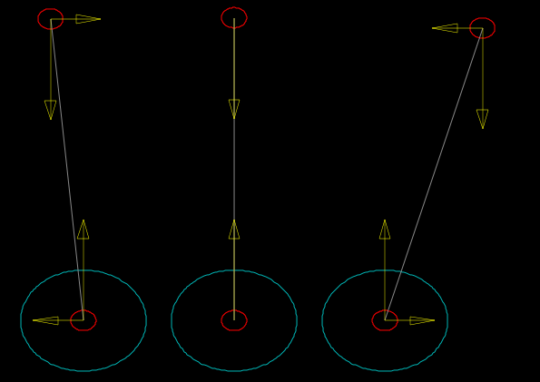
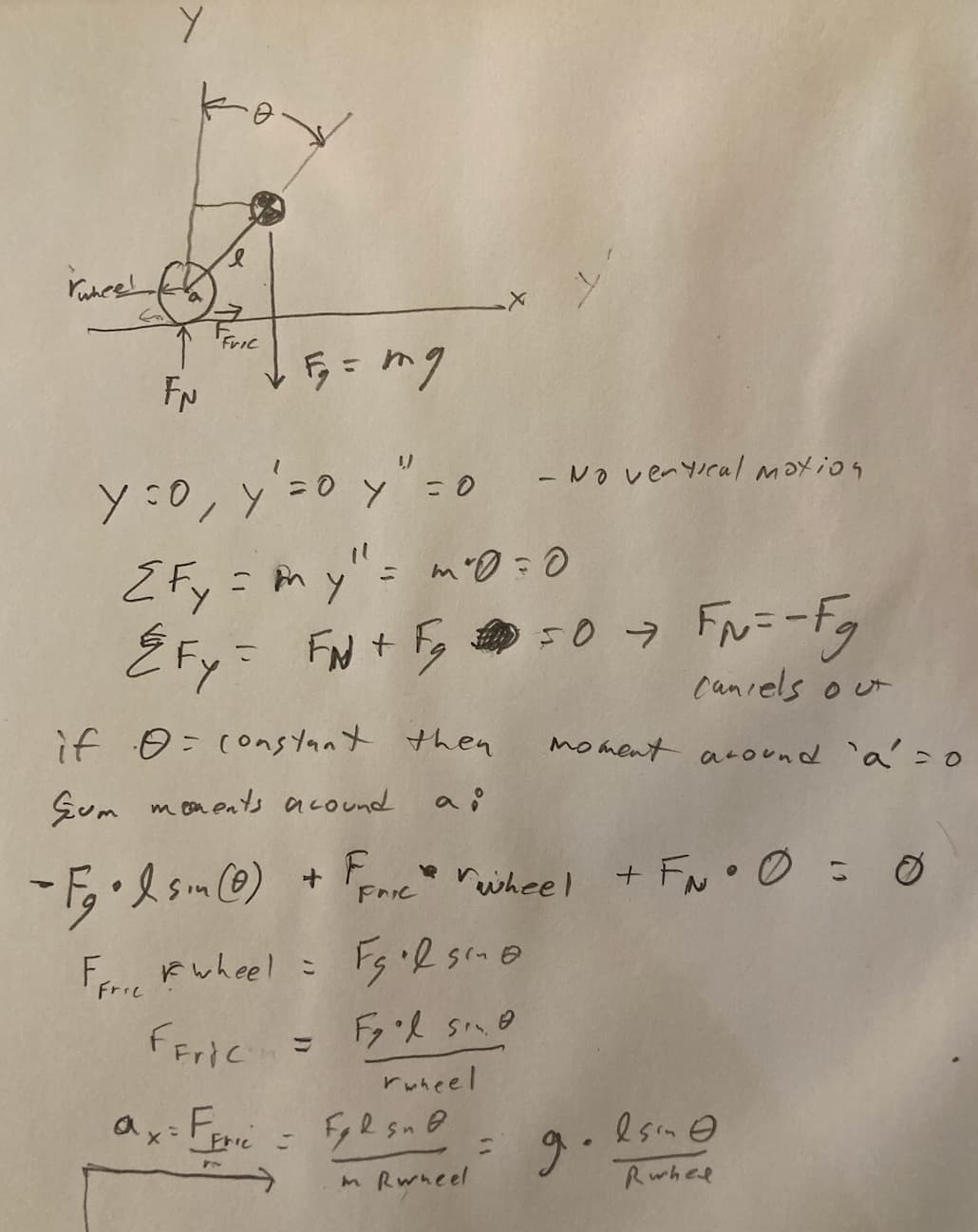
Try to draw the force balance that make the accelerations zero with this diagram:
If the combined center of mass isn't over the point of contact with the floor (tilt !=0), it needs torque to maintain the angle, which means the torque of the wheel has to be pushing the floor to the left, meaning the floor is pushing the cart to the right, and F=ma, accelerating the robot. You can't get zero acceleration (constant speed) at non-zero angles.
Those do not cancel -- one is the reaction force of the other. One acts on the ground, and its opposite force acts on the robot.
I think I was wrong here:
Since at angle a=45° you'd need to accelerate sideways at 9.8m/sec2 to balance the forces, and approaching 90° you'd need infinite acceleration. Both would quickly get you into the regime where air resistance would dominate.
It probably depends on the radius of the wheels and the height of the CoG above the axles, and some trig... maybe balancing torques around the axles:
-m g L sin(theta) = F_fric*R_wheel
F_fric = (m * g * L *sin(theta))/R_wheel
a_x = F_fric/m = g * L *sin(theta)/R_wheel

a_x = 9.81m/sec2 * sin(3°)*0.1m/0.05m = 1.02m/sec2
so with a 3° tilt, 10cm dia wheels, and 10cm CoG above axle, those speeds are about 1m/sec, 10m/sec, 1/100m/sec.
I doubt the steppers could deliver the torque at those RPMs.
i believe the system in general maintains equilibrium. the system is in equilibrium when the robot is tilted and moving at constant speed; neither speed nor angle is changing.
there are momentary small non-zero acceleration when 1) the tilt angle changes and 2) and the wheel speed changes.
lets say there is 1 ft/sec/sec acceleration by the wheels, the speed would be 1 ft/sec after a sec, 2 ft/sec after 2 sec, 10 ft /sec after 10 sec, ...
in equilibrium, 0 acceleration, moving left, still, moving right
all moment force must sum to zero during equilibrieum.
i don't know how the horizontal force at the wheel is generated
the force of the wheel on the floor (not shown) is equal to the friction forces on the motor. any excess force results in acceleration and an change in speed (see above)
because if there was a fairly accurate model of the system that showed how the bodies moved relative to the forces on them, that model could be used in a simulation using PID to simulate the complete system
Is it in equilibrium when it's running at constant speed?
I'm saying that when it has no acceleration (at zero or constant speed, neglecting drag), the angle is 0°. And that you can calculate the acceleration as a function of a constant angle.
A balancing robot has a different angle-speed relationship than a flying drone because a drone operates in conditions where air drag becomes more important.
ETA: For PID, this means the angle target should basically be zero. If you want a certain acceleration up to a different speed, like a yardstick, your speed curve needs to let it fall forward a tiny bit and then accelerate forward to rebalance vertically under the CoG at the target speed.