This, I'm not quite sure of. If you are treating the wheel and body together as one body, the internal forces and torques do not matter. If treating them separately, the moment due to gravity in the body could indeed be opposed by the torque of the motor on the wheels, but then you need to work out what balances the equal-and-opposite torque in the wheel system, and the only thing it could torque against is a net horizontal force on the the floor, and then applying F=ma gets you acceleration again.
you guys appear to continue to believe the only way the body/wheel is in equilibrium is when balanced directly over the wheel axle
i don't know how the body can remain balanced over the wheel axle (angle == 0) and move forward. where's the horizontal force that accelerates the body sideways to match the speed of the wheel come from? perhaps you guys can describe (equations, diagram) how that happens
i still don't see a serious discussion of how the force of gravity on the leaning body can results in a horizontal force, Fx (that exists with an unpowered motor)
How you draw the diagram matters in using being able to use math to figure out the forces. It's the same in lots of fields: In thermo, you draw a control volume around the part of interest and balance energy flows across the boundary. In electrical circuits you use Thevinin, Kirchoff's Current and Voltage laws to solve circuits. In programming, you write functions, APIs, and classes to draw boundaries around code. In all cases, if you are sloppy about the boundaries of the system component you are analyzing, you can get wrong answers.
Between an initial speed and a final speed, there is a transient acceleration phase, where one needs to pitch the balanced body into the acceleration. Though-experiment wise, consider a circus juggler balancing a broomstick on their palm in an airport, as they stop, start, walk on a people-moving conveyor, ride a shuttle, and take off and land in a plane. I think at each change in speed, they'd need a transient change in acceleration (with a transient change in angle). If the angle was speed dependent, the juggler who started balancing on the ground at zero speed and zero angle would have to balance the stick at a different angles at each speed, and angle X° at aircraft speed. If they started balancing a new stick on their other hand while on the plane at 0° and kept both sticks balanced though landing, then the first stick would be back at 0° but the second stick would have to be back at -X°. If the balance angle for an inverted pendulum was speed dependent, so would the angle of a non-inverted pendulum , and they would make excellent inertial compasses, much cheaper and more efficient than complicated gyrocompasses.
On the other hand, if the balance angle was transient with acceleration and returned to 0° at each constant speed, it would be more like our world.
That Kim and Sorensen paper does an excellent job of the diagram and the equations of motion.
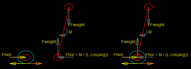
In this diagram, I think you are confusing statics and dynamics.
Is M mass?
If it is a statics problem and you constrain the (frictionless?) wheel to not move, and the weight to not rotate, then the vertical reaction force at the wheel is indeed -Fweight but the horizontal reaction force at the wheel of Fhor = m*g*tan(ang) and you need the opposing horizontal force on the arm point mass to constrain the rotation. (like a ladder leaning on a frictionless wall.)
If the arm is allowed to fall and rotate, it is a dynamics problem. And if the point mass of the weight of the arm is not resisted by friction of the wheel, or by the mass of the wheel, or by a constraint on the motion of the wheel, there's only the inertia (rotational and translational) of the arm resisting the fall. If the arm is a point mass, it has no "moment of inertia" (I = m*r^2 = m*0^2 = 0) and it takes no torque to accelerate the arm, and the vertical reaction force at the wheel is zero. It the arm has "moment of inertia", then the vertical reaction force would be produced by the dynamics of the angular acceleration of the arm.
You have to constrain the motion of the wheel to have horizontal force on the (massless) wheel.
if the wheel has some mass, won't the moment force accelerate both the wheel to the left Mwheel / Fhor as well as accelerate the CG of the body to the right Mbody / Fhor?
looks like you also need to account for the force of gravity accelerating the body downward Mbody/Fweight and the resistance to rotation by the moment of Inertia of the body
Solving the statics problem, and linearizing it into an error term that a PID can control is a problem that can be solved.
Well, sort of: If you draw a control volume around any robot pushing leftwards against the floor sufficiently to perfectly counteract/balance against a rightwards tilt of the CoG past the point of contact, no matter what complicated linkages, motors, transmissions, circuits, control programs, or AI within the robot, it will accelerate in the direction of tilt. Further I believe that the force is constant with a constant tilt, and that you can calculate that force, (and thereby the acceleration) with the equations of motion in the Kim & Sorensen paper, which all simplify greatly with the assumption of constant tilt angle.
Another way of thinking about it is that any horizontal force from the ground acting on the wheel of the robot is indeed opposed--opposed by the inertia of the robot.
Convinced by what? Kim & Sorensen's paper, diagram and math make sense to me, my diagrams and math make sense to me, you haven't shown errors in any of them and have instead proposed unrealistic thought experiments. No. I'm not convinced.
Sounds like you're convinced you can maintain an angle without accelerating.
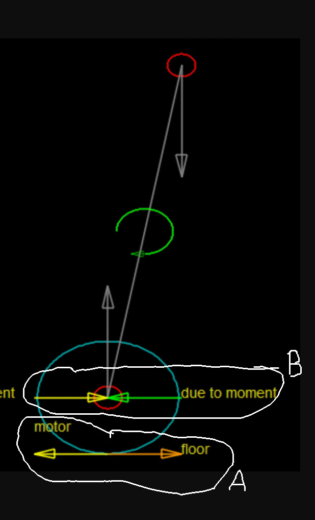
It's not the moment that accelerates the body, it is resisting the moment with the rightwards force of floor on the wheel.
the wheel on the left has no opposition and will accelerate
the center shows the body (without a wheel) and Fhor
the right shows the diagrams combined and that the fMot is opposed by Fhor
i believe the wheel/body won't accelerate because fMot is unopposed, that fMot == Fhor. that Fmot causes the wheel/body to move to the right, maintains it's speed. that because Fhor is opposed, the body remains at the same angle
The "green arrow due to moment" is part of a couple due to moment. If you place the bottom of a broom stick against a stop as you let it fall, and the force at the bottom of the broom is opposed by the stop, the top of the broom moves and accelerates to the right. Summing moments around the pivot point (and resolving them to a horizontal forces) produces an equal "force due to moment" working on the CoG:
If it were a ladder leaning statically against a wall, it would produce a "force due to moment" on leftwards the ground, and an equal and opposite "force due to moment" rightwards on the wall at the top.
If you take away the wall, and oppose the "force due to moment" with the inertia of the ladder, you again get F=ma.
 corrected