I am working on modifying a project another student at my college did with a 3.3V powered sensor. He used an Arduino UNO rev3 for it.
In order to fit the new additions to the project I have to basically recreate his circuit to make room and I noticed how, instead of powering the sensor from the 3.3V pin, he uses one of the 5V pins with a resistor and a zener diode.
I cannot think of any reason not to use the 3.3V and skip this component other than it might not be as reliable, specially when the line is also already being used for the serial communications voltage adapter.
This student is unavailable for comment and, knowing him, both him having a reason or just not thinking of using the 3.3V and going with a diode because he saw it in class are equally likely.
For context, here is also a crop of his schematic. LV1 is the serial level convertor and GND1 and GND2 are shorted together in the circuit. On the left are the arduino headers and on the right there is the header for the sensor.
The 3.3V pin is usually the output of a 3.3V linear regulator. That regulator could be a separate chip on the Arduino board, or, as is the case with the Nano clones, inside the CH340G USB adapter. Either way, it's going to produce a more stable output than the Zener circuit shown in your diagram. The problem is that the regulator will only handle so much current, and can overheat pretty easily. You would need to figure out how much current the 3.3V pin will have to supply. If it's under 100mA, you're probably ok. (Some here would suggest a lower number.) But even then you'd have to see how warm it gets. Above that, you would be pushing your luck.
Zener "regulators" are generally thought to be not very good regulators since the voltage will vary with the current, which is exactly what a regulator is supposed to prevent. They also waste a lot of power because the current draw is the same regardless of the load. What isn't used in the load gets shunted to ground through the Zener. So, oddly, the Zener is at risk of overheating when the load current is lowest.
If the 3.3V pin can't supply enough current for you, I would suggest you look at adding your own linear regulator. It would just be the regulator and two capacitors, versus the Zener and the resistor, so only one additional part. Something like the MCP1700 or 1702 might be a good choice. They come in a TO-92 package.
If space or parts count is critical, and you enjoy living dangerously, and if the devices being powered from 3.3V are always turned on, you could supply most of the current they need directly from the 5V source through a resistor, enough to bring the voltage up to, say, 2.8V under load, and have the 3.3V pin just top things off and bring it on up to 3.3V. I hope I don't have to point out how dangerous this is. But it does work. I had a Commodore computer that was powered exactly that way. Most of the heat is dissipated in the resistor, but the output is still a regulated 3.3V.
I don't believe this is correct:
"That regulator could be a separate chip on the Arduino board, or, as is the case with the Nano clones, inside the CH340G USB adapter. "
CH340G does not supply 3.3V current. The 3.3V pin just tells the chip what the IO level.
"connects of VCC to input outside power while 3.3V, connects of 0.01uF decoupling capacitance outside while 5V"
"CH340 chip supports 5V and 3.3V power voltage. When using 5V source power, the VCC input 5V power and the pin of V3 must connect with 4700pF or 0.01uF decoupling capacitance. When using 3.3V power voltage, connects V3 with VCC, and input 3.3V power voltage. And the other circuit voltage which is connected with CH340 is no more than 3.3V."
Nano boards equipped with FT232 can support 50mA of 3.3V current from the FTDI chip.
I admit to not having tested it, but I did say "Nano clones", which may not be described by the Sparkfun documentation. The schematic I was referring to is this one:
It shows the 3.3V pin of the CH340 connected to the 3.3V pin of the Nano. But I don't know how much current it can source. Probably not very much, and probably less than the FTDI would supply.
The Uno and Mega have a separate 5-pin 3.3volt/150mA voltage regulator,
that isn't used for anything else on the board.
The (classic) Nano taps 3.3volt from the internally regulated 3.3volt supply of the CH340 USB chip (pin5),
and that voltage stays rather stable up to about 30mA.
I wouldn't draw more than 30mA from that pin, since it's unspecified in the datasheet.
Leo..
The later model detectors such as the TGS2611 require only 60 mA for the heater, however the older sensors require 170 mA which is clearly more than what you can reliably expect from the 3.3 V auxiliary regulator (whatever that may be) on a "Arduino" (which may be a clone).
Yes, and in fact the Zener regulator in the drawing supplies 170mA if it is driven from 5V ((5-3.3)/10). So if that's the kind of current the OP is looking at, something like a 250mA regulator would need to be added. Or use the Zener circuit.
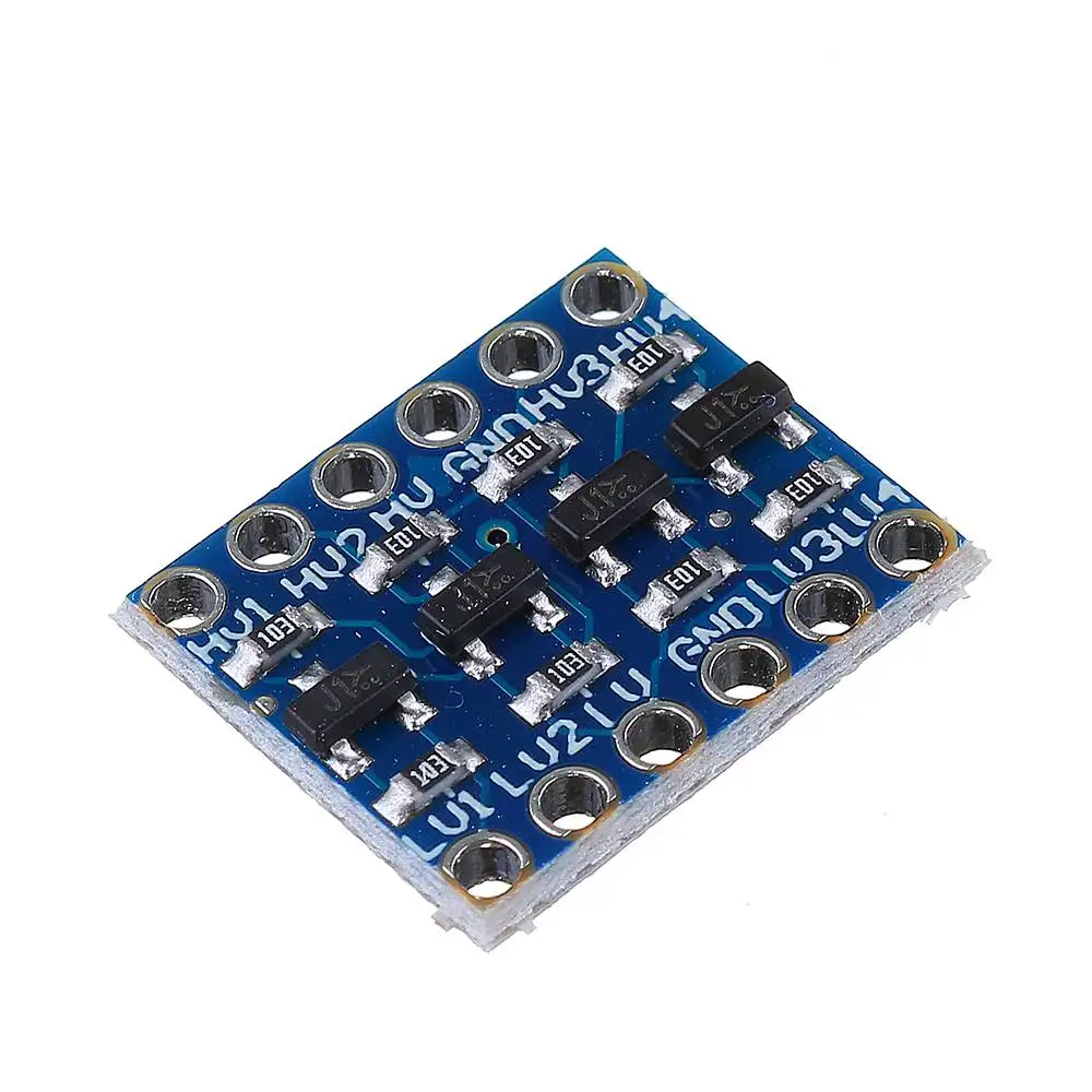
"LV1" is a bidirectional level converter board; one of these:
That said, why a gas detector would operate at 3.3 V and why a level converter would be an appropriate interface, that I cannot figure.