That's a bad circuit. You cannot use the base current to control the collector voltage,
transistors don't work like that.
The base resistor sets the base current. For a switching transistor you want the
base current to be high enough to saturate the device, bringing the collector
right down to 0.1V or so. The current for the LED is set by having a current-determining
resistor in series with the LED.
You cannot do it with the base because the gain of a transistor is not at all stable or
predictable - it varies with:
o temperature
o collector current
o collector voltage
So we never rely on the gain being exact.
With analog circuitry feedback from collector to base is often used to bias the
transistor into the correct operating area - negative feedback trades gain for
accuracy, in particular the resulting gain is much less sensitive to the transistor
gain, and much more determined by the feedback network.
Here we are switching, so saturation is needed. To saturate the base current
needs to be many times higher than for linear circuits. Perhaps 3 to 5 times higher.
If your LED needs 20mA and has a forward voltage of 1.9V (typical red LED), then
there is 1.9V across LED, 0.1V across saturated transistor, leaving 3.0V across
the current-limiting resistor. Thus you would use a 150ohm resistor (3V/20mA) between
collector and LED, and the base current should be about 1mA, therefore 4k7 base
resistor would work nicely.
If the transistor has a gain of 100 we are setting the collector to base current ratio at
20 - giving it fives times as much base current to ensure proper saturation.
The 2n2222 is the wrong transistor, it cannot take 700mA and saturate when driven
by an Arduino pin (it can't even saturate with 50mA base current trying to give
500mA collector current (Vce = 1.0V)) - the Arduino pin can only give about 30mA
before you risk overloading it (absolute max = 40mA).
You need a better transistor or one that can dissipate more power without
overheating, or a logic-level MOSFET.
My favoriate high current switching transistor is the ZTX851, give it 30mA
of base current and it'll handle over an amp without overheating.
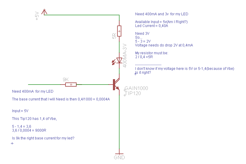
This is the first problem. Since LEDs are current driven, you actually want a particular current to flow through the LED when the transistor is on. To limit the current, you need a resistor in series with the LED. You can find lots of tutorials on how to pick the series resistor for a particular LED and power supply; none of the details change significantly just because you have a transistor acting as the switch instead of just wires. For 450mA through a 3V Vf LED and 5V supply, you should have a resistor of about 5 ohms (and you should figure out how I got that...)
Now, the transistor is also a current-operated device. When you put a current into the base, the transistor will allow a current of up to Ibase*gain to flow through the collector/emitter path. Just like with an LED, you need to limit the current into the base to a level that is safe for both the transistor AND the AVR pin providing the current. That means about 30mA. Using the same formulas used for LEDs, and assuming that the Base Voltage drop is .7V (typical for Silicon bipolar transistors), you should use a base transistor of about 150 ohms.
Then you start to run into the practical issues that MarkT mentions. For the transistor to act as a switch and be fully ON, so that the output circuit behaves like we want, the gain of the transistor should be significantly greater than Ic/Ib
(450/30, or 15.) (Significantly greater ideally means something like 5x or more, not G+5) If you look at a datasheet (I'm actually looking at a PN2222A; an actual 2n2222 is probably a rarity these days), you'll see that the typical gain is 100 to 300, so that should be fine, right? No; the gain is dependent on the collector current; reading more carefully, at Ic = 500mA, the gain might be as low as 40. Less than 3x the gain we were hoping for. Which makes it a bit ... questionable.
I would go ahead and wire it up, check the LED brightness, measure the currents, and see if the transistor gets overheated. (This would probably not be risky for the Arduino, but you could also test it with just a wire from the base resistor to +5V or GND...)
To limit the current, you need a resistor in series with the LED
This is ok for small leds of about 20 mA
Your big 1W (400 mA) led needs a current source of about 300 to 450 mA, which is something different than a 5V voltage source.
This is the first problem. Since LEDs are current driven, you actually want a particular current to flow through the LED when the transistor is on. To limit the current, you need a resistor in series with the LED. You can find lots of tutorials on how to pick the series resistor for a particular LED and power supply; none of the details change significantly just because you have a transistor acting as the switch instead of just wires. For 450mA through a 3V Vf LED and 5V supply, you should have a resistor of about 5 ohms (and you should figure out how I got that...)
Now, the transistor is also a current-operated device. When you put a current into the base, the transistor will allow a current of up to Ibase*gain to flow through the collector/emitter path. Just like with an LED, you need to limit the current into the base to a level that is safe for both the transistor AND the AVR pin providing the current. That means about 30mA. Using the same formulas used for LEDs, and assuming that the Base Voltage drop is .7V (typical for Silicon bipolar transistors), you should use a base transistor of about 150 ohms.
Then you start to run into the practical issues that MarkT mentions. For the transistor to act as a switch and be fully ON, so that the output circuit behaves like we want, the gain of the transistor should be significantly greater than Ic/Ib
(450/30, or 15.) (Significantly greater ideally means something like 5x or more, not G+5) If you look at a datasheet (I'm actually looking at a PN2222A; an actual 2n2222 is probably a rarity these days), you'll see that the typical gain is 100 to 300, so that should be fine, right? No; the gain is dependent on the collector current; reading more carefully, at Ic = 500mA, the gain might be as low as 40. Less than 3x the gain we were hoping for. Which makes it a bit ... questionable.
I would go ahead and wire it up, check the LED brightness, measure the currents, and see if the transistor gets overheated. (This would probably not be risky for the Arduino, but you could also test it with just a wire from the base resistor to +5V or GND...)
Hi! First of all, thank you for your explanation..
We... I've searching on internet and found out some formulas and Now I'm testing one and actually I'm having the base transistor at about 4mA and the led current is about 420mA.
The Brightness is grat and under its maxtimum current(700mA).
The LED is handling about 420mA but the 2n2222 IS overheating. I can't even touch. I have changed the base input to to 2ma, providing about 200mA of LED current and the 2n222 keeps hot(really hot)
I Have tested another 2n2222 and same overheating problem...
That's normal.
The transistor does not run as a switch and dissipates about 2V * 400mA ~ 1W of heat.
( It's rated for max 500 mW, so even cooling it with a heatsink won't help )
That's normal.
The transistor does not run as a switch and dissipates about 2V * 400mA ~ 1W of heat.
( It's rated for max 500 mW, so even cooling it with a heatsink won't help )
Hi Michael. Thank you for your answer!
Could you tell me wich one could do the job without overheating?
Well, I would not go for a bigger transistor but use a different design:
If this 5V source is a given, and you got that 2N2222 already, westfw's 4.7Ohm (1W) resistor with a base resistor of 330 Ohm (for more than 10mA base current) to your transistor will do the trick.
Alternatively:
Get a ready built 350mA current source ( usually fed by 12V ) and use your transistor with a smaller base resistor to have about 10mA base current as a switch. (better use a logic level mosfet as a switch)
Bear in mind darlingtons don't saturate, since the collector is held at about 0.8 to 1.5V
above the emitter due to the configuration. So you'll probably get about 1/2 a watt of
heat from it. At least it has a metal tab for a heatsink.
2N2222 isn't going to handle 400mA continuous comfortably without a lot of current into
the base, perhaps 60mA, to bring the Vsat down. You could try driving it again with a
base resistor of 150 ohms, giving about 30mA base drive (the most that's safe for an
Arduino). 330 ohms is a bit too high. It will still run hot, its a small package.