How to connect reed switches to 74HC165?

I'm using this circuit diagram to connect 8 reed switches to a PISO shift register (74HC165) -

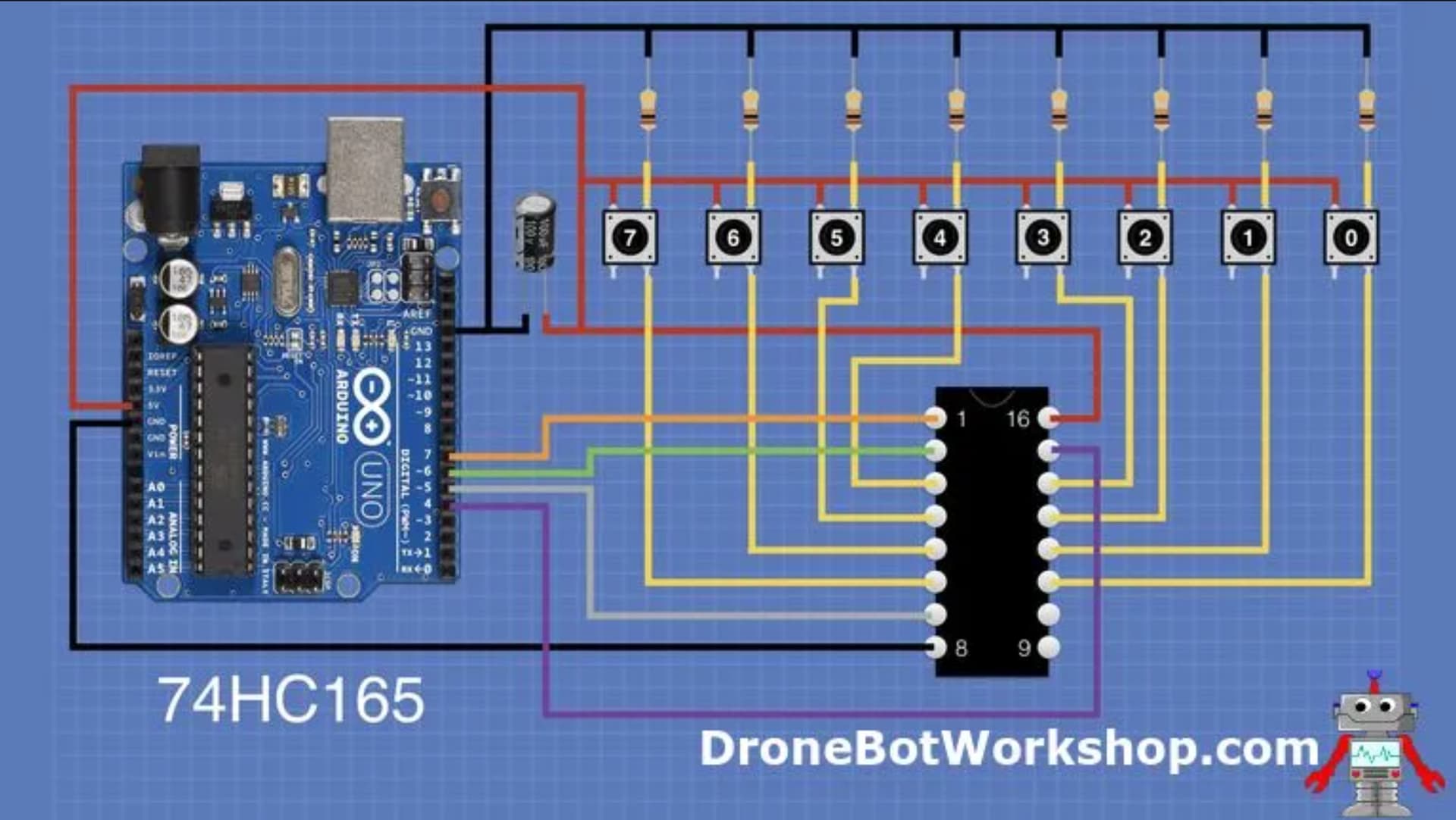
Instead of the push buttons, I want to attach reed switches. I've done that by connecting one end of each reed switch to 5V, and the other end to an input of the 74HC165 via a 22k resistor. I am using this sketch to read data -

int load = 7;
int clockEnablePin = 4;
int dataIn = 5;
int clockIn = 6;

void setup() {
  Serial.begin(115200);
  pinMode(load, OUTPUT);
  pinMode(clockEnablePin, OUTPUT);
  pinMode(clockIn, OUTPUT);
  pinMode(dataIn, INPUT);
}

void loop() {
  digitalWrite(load, LOW);
  delayMicroseconds(5);
  digitalWrite(load, HIGH);
  delayMicroseconds(5);

  digitalWrite(clockIn, HIGH);
  digitalWrite(clockEnablePin, LOW);
  byte incoming = shiftIn(dataIn, clockIn, LSBFIRST);
  digitalWrite(clockEnablePin, HIGH);

  Serial.print("State: ");
  Serial.println(incoming, BIN);
  delay(200);
}

However, I always get the output as 11111111, and the reed switches don't seem to detect when I bring a magnet nearby. What am I doing wrong?

Do you forget to add a pulldown resistors - as in the diagram above?
Screenshot from 2024-04-10 11-19-35

Indeed, because the inputs of 74HC165 are floating without of the external pulldowns.

Please don't use that code. The 74HC165 is normally used with the Clock Enable connected to GND and using the Latch pin and without shiftIn().
When using shiftIn(), the data might be collected at the very edge of the clock pulse.

The Wokwi simulation has a 74HC165: https://docs.wokwi.com/parts/wokwi-74hc165
If you scroll down, then you see working examples. The first example is what you want.

Wokwi has push buttons, that can be kept down if you want (with the Ctrl key), and it has slide switches and dip switches.

If you write down your circuit with a pen and make a photo of it, that would be very helpful for us. You can also make a photo of your project.

That sounds incorrect, from your description.

I would recommend connecting the 22K between the 74HC165 input and 5V. Connect the reed switch between the 74HC165 input and ground.

2 Likes

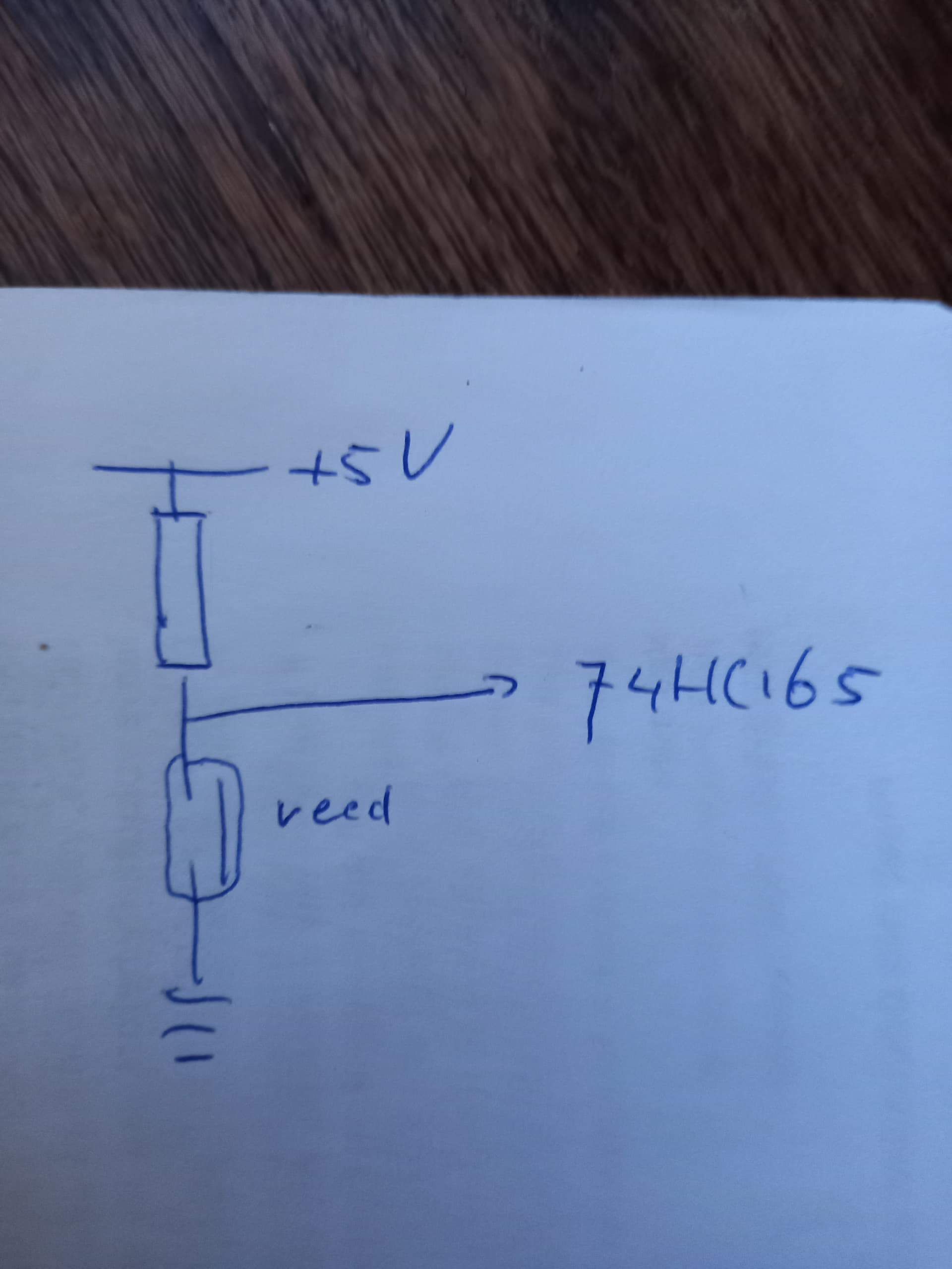
If the reed contact is open, it will result in a HIGH, if it's closed it will result in a LOW. If that's the wrong way around, you can swap the resistor and the reed contact or change the code to cater for it.

1 Like

It isn't "wrong way around". It's a perfectly valid way of testing if the reed switch is open or closed. Just as valid as if you swap the resistor and reed switch.

The advantage is that you don't need to route 5V over potentially long wires to where the reed switch is situated. If you did that, and the 5V wire became broken or disconnected, it could cause a short circuit which could damage components or the power supply. But with my suggested wiring, if the wire gets damaged or disconnected and a short circuit occurs, the resistor limits the current, preventing damage.

1 Like

This worked, thank you!

This topic was automatically closed 180 days after the last reply. New replies are no longer allowed.