I'm connecting my controller to a small speaker (8ohm, 0,25w).
I've got two variants of connecting the speaker, but do not know which is the "right" one, if it matters. Can someone tell me if there is a correct version?
There is also talk about putting a diode or 47uf capacitor to protect the transistor. I think this is between the + of the speaker and ground, is that correct?
What you have is an inductive load, and every time the transistor is turned off, it generates a flyback voltage. To protect the transistor, you can add a flyback diode (e.g., a 1N4007) across the speaker terminals, with the cathode (stripe) connected to the positive terminal and the anode connected to the negative terminal.
Alternatively, you could use an N-Channel MOSFET, which often performs better for switching inductive loads due to its lower RDS(on)R_{DS(on)}RDS(on).
Important Notes:
Power Source:
Do not power the speaker from the 5V terminal of the Arduino. The Arduino's 5V pin is not designed to supply significant current and could be damaged. Use a dedicated power supply for the speaker.
Base Resistor:
Increase the value of the base resistor for your transistor. At 5V, a typical resistor might draw too much current from the controller, around 45mA in your case, which could exceed the Arduino’s maximum current rating. Ideally, the base current should be less than half the maximum current rating of the microcontroller pin.
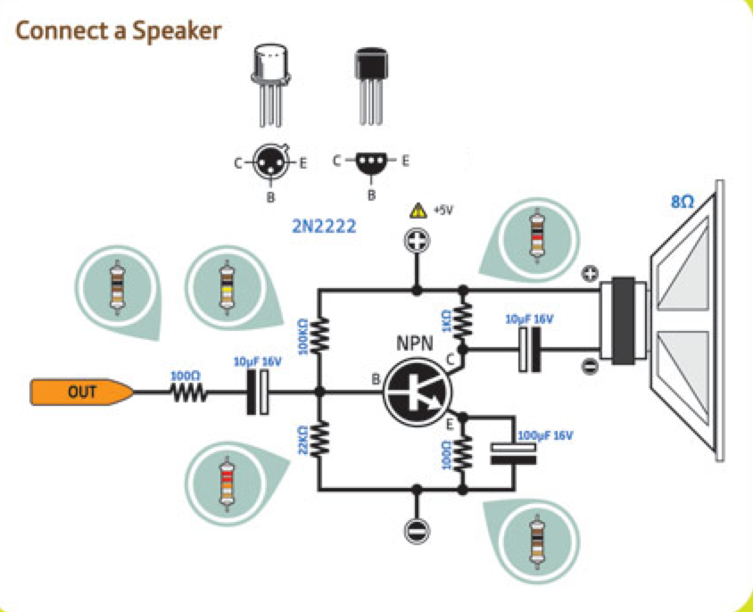
Think of your speaker as an electric motor designed to move a diaphragm back and forth to move a volume of air. That movement requires an AC current. Your design applies a DC current to the speaker/motor, which locks the diaphragm, except for a pulsing movement. The speaker must have a capacitor in series with it so the DC part of your connection is removed from the speaker/motor.
Neither of your circuits will give more than a tiny sound from the speaker.
I did not specify the endgoal. It is to provide sound effects (christmas edition, like a jingle or bells or a 'hohoho'.) in an office room after being trigged. Not too loud, but audible inside.
I thought to use the "5V Step-Up Voltage Regulator U1V10F5 Pololu 2564" as a 'source' with a 3 aaa batterycase behind that.
Besides if this is thé way or not, at least I've learned that powering a separate source is often preferred if possible.
Luckely I have a 1N4007 lying around in a pack I got last year. Really helpful to know why and where to place it, so thanks for this nugget!
I did try a 1k resistor instead of the 100 ohm one. I did sound less loud of course. I wonder if filtering the DC will better this..
Thanks for the removing of DC advice. Only when searching for this specific information I got to find information about this! Does this removal amplify the 'tiny' sound? The site mentioned in my first post uses the transistor specifically because it amplifies (somewhat).
I do not know what your "tiny sound" is, but all the sounds created are only simulated when you use digital to create them. After all, a 0 to 5 volt change is a far cry from a + - 5 volt signal.
I was referring to what you wrote with the 'tiny' sound. TBH I have to test it in the office next week or so to know if it's loud enough or not. When I had it set up like Variant 1 I think it just passed as for it's volume.
I did have a working project, just wondered why some people online are putting the speaker inline with the vss-line or others inline with the ground-line.
If there are any tips to make it louder with minimal components, that's always a win in my book! Your tips about the diode and the cap to remove DC are gold as well.
If you want to make the signal louder, integrate the signal, remove the DC component by placing a capacitor in series, and then feed it into an audio amplifier. This will ensure a clean, amplified output for your application.
Forget about your proposal. It is likely to blow your speaker.
Do the math...
5V/8ohm>0.5A
0.5A×5V=2.5W.
And because the DC component is in, your speaker membrane will be at its utmost position...
Find an audio amplifier (you can even build one with one transistor. .).
A piezo speaker may be easier...
Or a 16 ohm speaker...
Any transistor can have a number of different pin out patterns. Best check the actual one you have with a transistor tester that will tell you the pinout.
Flailing that if you use a DVM on continuity then the base is the one that looks like a diode between two of the pins. That is if you find two pins that give you continuity swap the leads of your DVM over and it should look like a high resistance.
Just checked my stock of 2N2222 and yes you are correct.
However, on a transistor with the emitter and collector swapped it will still work only with lower gain. I once got asked this in a job interview and gave this answer and the interviewer said "I use this question to differentiate between people with real experience and not just book learnt stuff".
As I is not my source diagram I will attempt to change it at the image level.
EDIT
I have now done this and replaced the original diagram from post#13