Hello! I'm a total coding newbie, so my question may seem funny and the code may not be professional. I have a question about connecting two MT6816 encoders to Arduino Nano. Standard connection pins 13, 12, 11, 10 (csn1), 9 (csn2), 5V, hvpp connected to vdc (SPI mode). Each one works great, both connected give a result of 0, after disconnecting one the other works and vice versa. I have no idea how to solve this, I tried various combinations of code and connections, but nothing had any significant effect.
I would be very grateful for any tips. And this is the code I used:
#include <SPI.h>

const int CS_PIN = 10;
const int CS_PIN_2 = 9;

bool click = false;

const byte READ = 0x83;

void setup() {

  Serial.begin(9600);

  pinMode(CS_PIN, OUTPUT);
  digitalWrite(CS_PIN, HIGH);

  pinMode(CS_PIN_2, OUTPUT);
  digitalWrite(CS_PIN_2, HIGH);

  SPI.begin();

  SPI.setClockDivider(SPI_CLOCK_DIV16);
  SPI.setDataMode(SPI_MODE3);
  SPI.setBitOrder(MSBFIRST);
}

void loop() {

  if (click == false)
  {
    uint16_t angleData = readAngleData();
    Serial.print("Angle_1: ");
    Serial.println(angleData);
     click=true;
     delay(500);
  }

  if (click == true)
  {
    uint16_t angleData = readAngleData_2();
    Serial.print("Angle_2: ");
    Serial.println(angleData);
     click=false;
     delay(500);
  }

}
//-------------------------------------------------------
uint16_t readAngleData() {

    digitalWrite(CS_PIN, LOW);

  SPI.transfer(READ);

  uint8_t highByte = SPI.transfer(0x00);
  uint8_t lowByte = SPI.transfer(0x00);

  digitalWrite(CS_PIN, HIGH);

  uint16_t result = (highByte << 8) | lowByte;

  uint16_t angle = (result & 0x3FFF);

  return angle;

}
//-------------------------------------------------------

uint16_t readAngleData_2() {

  digitalWrite(CS_PIN_2, LOW);

  SPI.transfer(READ);

  uint8_t highByte = SPI.transfer(0x00);
  uint8_t lowByte = SPI.transfer(0x00);

  digitalWrite(CS_PIN_2, HIGH);

  uint16_t result = (highByte << 8) | lowByte;

  uint16_t angle = (result & 0x3FFF);

  return angle;

}
jim-p
March 1, 2025, 1:16pm
2
You can only read one byte at a time.
The if click == true/false does nothing.
Show the code you have where it works with only one connected.
Thanks for your reply, I'll check the suggestion and let you know how it goes. This code also works with one encoder, but I'm posting the basic code for one encoder below:
#include <SPI.h>

const int CS_PIN = 10;

bool click = false;

const byte READ = 0x83;

void setup() {

  Serial.begin(9600);

  pinMode(CS_PIN, OUTPUT);
  digitalWrite(CS_PIN, HIGH);

  SPI.begin();

  SPI.setClockDivider(SPI_CLOCK_DIV16);
  SPI.setDataMode(SPI_MODE3);
  SPI.setBitOrder(MSBFIRST);
}

void loop() {

    uint16_t angleData = readAngleData();
    Serial.print("Angle_1: ");
    Serial.println(angleData);
     click=true;
     delay(500);

}
//-------------------------------------------------------
uint16_t readAngleData() {

  digitalWrite(CS_PIN, LOW);

  SPI.transfer(READ);

  uint8_t highByte = SPI.transfer(0x00);
  uint8_t lowByte = SPI.transfer(0x00);

  digitalWrite(CS_PIN, HIGH);

  uint16_t result = (highByte << 8) | lowByte;

  uint16_t angle = (result & 0x3FFF);

  return angle;

}
//-------------------------------------------------------
jim-p
March 1, 2025, 3:26pm
4
OK
Either use a MUX/switch or use software SPI for the other encoder.
One way to do it
1 Like
Oh thanks! When I buy it I'll try to work it out!
I tried again with the code, I added a line of code at the beginning of the function:
SPI.beginTransaction(SPISettings(20000000, MSBFIRST, SPI_MODE3));
and at the end of the function:
SPI.endTransaction();
and now I have readings from two encoders, but the readings are incorrect, only after disconnecting one or the other the readings are correct.
and this is the whole code:
#include <SPI.h>

const int CS_PIN = 10;
const int CS_PIN_2 = 9;

const byte READ = 0x83;


void setup() {

  Serial.begin(9600);

  pinMode(CS_PIN, OUTPUT);
  digitalWrite(CS_PIN, HIGH);

  pinMode(CS_PIN_2, OUTPUT);
  digitalWrite(CS_PIN_2, HIGH);

  SPI.begin();

  SPI.setClockDivider(SPI_CLOCK_DIV16);
 // SPI.setDataMode(SPI_MODE3);
 // SPI.setBitOrder(MSBFIRST);
}

void loop() {


    uint16_t angleData = readAngleData();
    Serial.print("Angle_1: ");
    Serial.println(angleData);
     delay(500);

    uint16_t angleData_2 = readAngleData_2();
    Serial.print("Angle_2: ");
    Serial.println(angleData_2);
     delay(500);

}
//-------------------------------------------------------
uint16_t readAngleData() {


  SPI.beginTransaction(SPISettings(20000000, MSBFIRST, SPI_MODE3));  // added line

  digitalWrite(CS_PIN, LOW);

  SPI.transfer(READ);

  uint8_t highByte = SPI.transfer(0x00);
  uint8_t lowByte = SPI.transfer(0x00);

  digitalWrite(CS_PIN, HIGH);

  uint16_t result = (highByte << 8) | lowByte;

  uint16_t angle = (result & 0x3FFF);

  return angle;

  SPI.endTransaction(); // added line
}
//-------------------------------------------------------

uint16_t readAngleData_2() {

  SPI.beginTransaction(SPISettings(20000000, MSBFIRST, SPI_MODE3));  // added line

  digitalWrite(CS_PIN_2, LOW);

  SPI.transfer(READ);

  uint8_t highByte = SPI.transfer(0x00);
  uint8_t lowByte = SPI.transfer(0x00);

  digitalWrite(CS_PIN_2, HIGH);

  uint16_t result = (highByte << 8) | lowByte;

  uint16_t angle = (result & 0x3FFF);

  return angle;

  SPI.endTransaction();  // added line
}
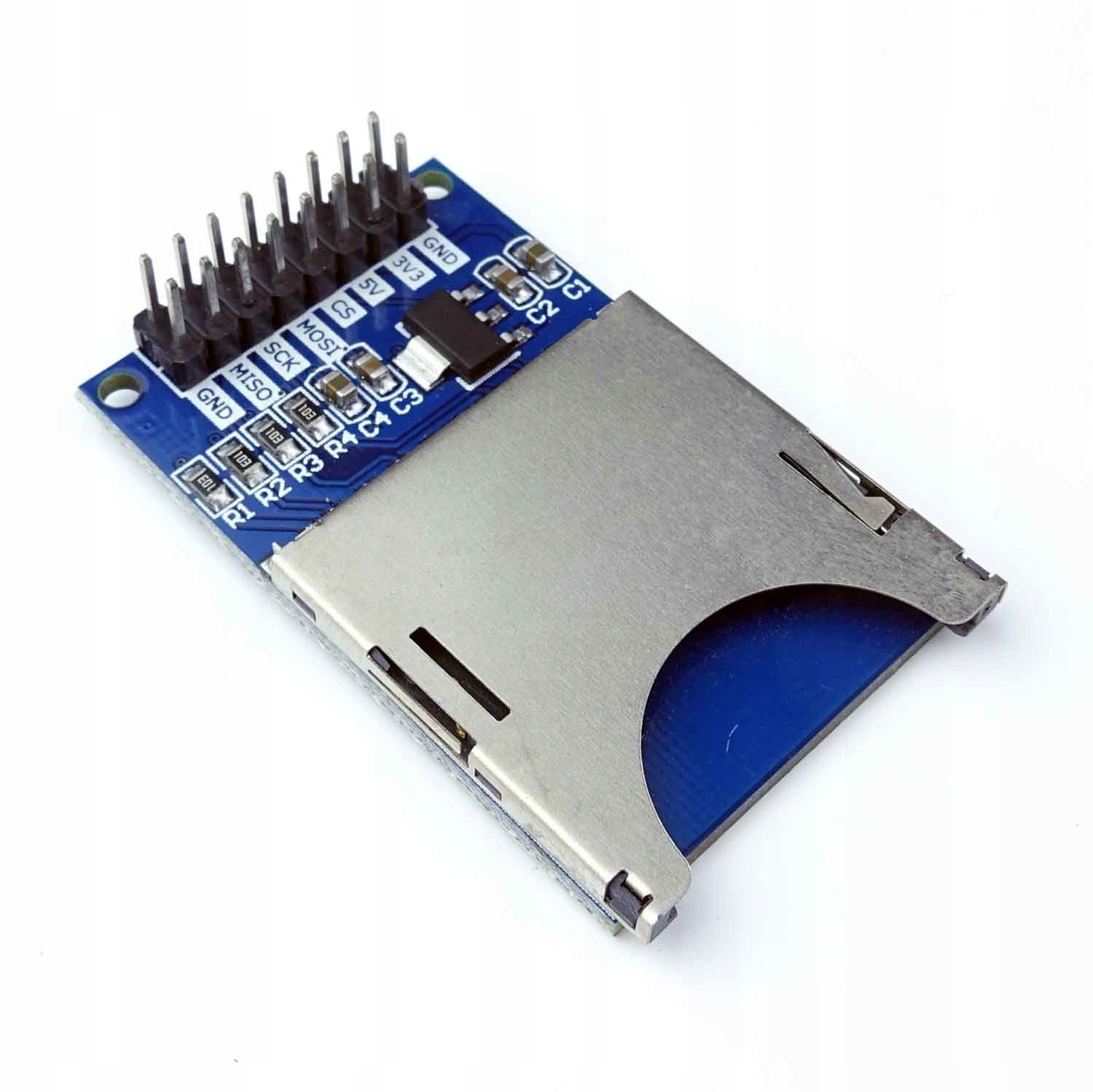
That's exactly what I'll have to do. I have one more question, in this system there will also be an SD card reader, which also uses these pins, but writing will only be after reading the data from the encoder, so I have to connect the reader to the 74hct125 to pins 8, 9, 10 or 11, 12, 13?
jim-p
March 2, 2025, 3:14pm
10
Connect the encoders as show below.
1 Like
Thank you very much for this valuable information!
Still doesn't work, I need to check the wiring. What about connecting CS from encoders to pins - 74hct125 pins 1 and 4?
jim-p
March 4, 2025, 4:47pm
13
I guess I was not clear about that.
It seems to have started working!
Thank you very much!!!
Encoders work great! However, the SD card reader refuses to work. I also connected via 74hct125, but it does not initialize the card, if I disconnect the MISO encoders, the card is initialized.
jim-p
March 5, 2025, 8:34am
17
There are dozens of SD readers. Some people have problems with certain versions.
jim-p
March 5, 2025, 8:52am
18
Make sure that the CS lines for each encoder is high, That should automatically disconnect the encoder MISO line.
I have a 3.3V and 5V reader, but during testing only 3.3V gave correct file saving. I noticed that when I initialize the CS encoder pins in the setup function before initializing the SD card, the card reader works and saves correctly, but the encoder does not, it shows the first reading phrase and the next ones are zeros.
And these are the setup function settings:
void setup() {

  Serial.begin(9600);

  pinMode(CS_PIN, OUTPUT);
  digitalWrite(CS_PIN, HIGH);

  pinMode(CS_PIN_2, OUTPUT);
  digitalWrite(CS_PIN_2, HIGH);

  pinMode(POM, INPUT_PULLUP);    // button

  if (!SD.begin(SD_CS))
    {
      Serial.println("CARD OR READER PROBLEM!");
      while (1);
    }
    else
    {
      Serial.println("CARD OK!");
    }

  SPI.begin();

  SPI.setClockDivider(SPI_CLOCK_DIV16);
  SPI.setDataMode(SPI_MODE3);
  SPI.setBitOrder(MSBFIRST);

}
jim-p
March 5, 2025, 11:05am
20
Which sd card library are you using?