I am new to Arduino and to electronics so I have a lot to learn. I have read a little on capacitors and understand what they do and a few of the use cases. However, I struggle on how to determine or how to calculate the capacitor value needed. I understand that the voltage part in that it must be large enough for the circuit. But how do you determine how many farad a capacitor in a self-built circuit needs?
If you're building a circuit someone else has designed then they'll tell you. If it's your own design of circuit then looking at one that's very similar might help.
But capacitors have all sorts of different purposes so it would help if ask about a specific circuit you're interested in building. In some cases like e.g. RF oscillators, the value (and type) are critical. In other cases like a lot of decoupling caps values are a lot less important.
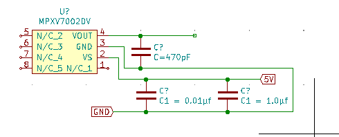
Thanks for your replies wolframore and slipstick. I have attached two small examples from a circuit I am trying to build. I have copied these from others on the net - so they may not be right.
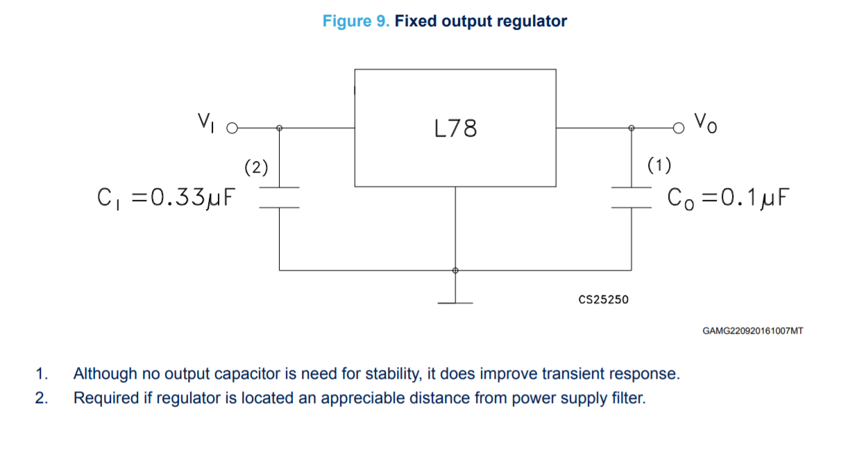
Both those examples are for filtering and they are critical. They are also the minimum values recommended from their datasheets. I haven’t used the pressure sensor but I know for certain the that regulator will not work without the caps.
The caps that’s are connected to power and ground are called bypass caps. They work by passing high frequency to ground while blocking DC (to ground). This cleans up some of the noise thats generated by the circuit. For instance that output filter cap for the 7805 helps to clean up the output, this filtering is necessary so that the 7805 won’t oscillate trying to regulate noise.
If you have an oscilloscope you can watch this noise. Take the cap out and see what happens.
The value calculation gets a little involved and again depends on the circuit and what noise you’re dealing with. Unless you like doing calculus use the recommendations. Experimentation can be done if you can see what’s happening.
Couple things to remember caps pass AC and block DC.
wolframore:
If you have an oscilloscope you can watch this noise. Take the cap out and see what happens.
A very interesting experiment indeed - just as interesting: check the noise on the other end of the power rail of the breadboard as well. Same power rail... nominally the same... but it can look very different!
wolframore:
For instance that output filter cap for the 7805 helps to clean up the output, this filtering is necessary so that the 7805 won’t oscillate trying to regulate noise.
If you have an oscilloscope you can watch this noise. Take the cap out and see what happens.
I don't have an oscilloscope but AFAIK datasheets of those old regulators usually state the output cap is NOT needed for stability (in other words they will not oscillate); it "only" improve transient response. If you truly did this experiment can you post the pictures?
I'll test both... it's been a while since I've used 78xx... I have tons of them still... it's still recommended. All the linear regulators are a tradeoff.
I'll set them both up for Vin= 12V and we can vary the loads... let's do a lab!
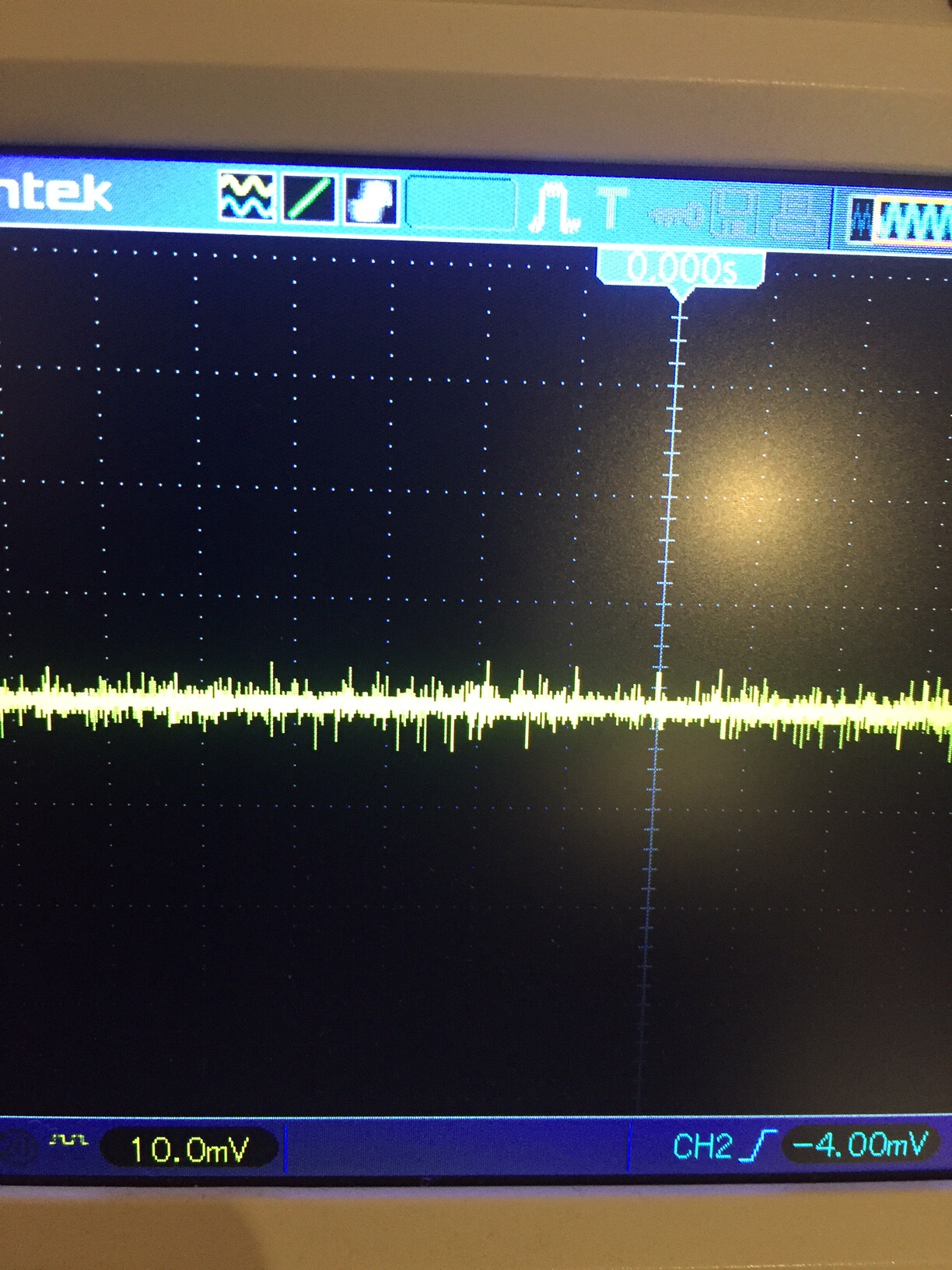
I found a 7808 - don't ask why I have those... no clue can't find any of my others. I mainly use SMD these days:
Here's the set up. Smajdalf is correct, regulation is fine without the output cap. I'm feeding then 12V. Keep in mind this is in a controlled environment so steady input voltage.
Sometimes a capacitor is used for decoupling - to stiffen up the supply rail voltage against change
as the load changes, especially at high frequency where the rail is high impedance due to its inductance.
The size of a cap for decoupling depends on the current fluctuations of the load, the permissable voltage
fluctuations and the frequency. Each package of charge flowing into or out of a cap changes its voltage, the
formula is dV = Q/C, Q is the charge in coulombs, dV is the change in voltage in volts, C is the capacitance in
farads. Thus C = Q/dV
Sometimes a capacitor is used to set a time constant for a filter, in cooperation with a resistor. Here the
formula is t = RC, so C = t/R (for instance for a 1 millisecond time constant with a 1k resistor you need a
1µF capacitor.
In an LC tuned circuit 1/LC = (2πf)^2 (where L is inductance in henries, C in farads, f in hertz). So for
a 1MHz frequency with a 1µH inductor the cap should be about 25nF
So you apply the formula relevant to the use-case.
All of these results can be derived from the differential equation for an ideal capacitor:
I dt = C dV ( also can be written dV/dt = I/C )
I tried the 7805 without capacitors and an actual load on it; didn't work at all. Adding a small film(at the time no ceramics at hand) capacitor made all the difference.
No power got delivered to the project it was supposed to be powering - a NodeMCU with a bunch of sensors, iirc, it's been several years since I tried that. Probably also a small air pump, 200-300 mA or so for that. Needed 5V for it, anyway. Adding the caps made all the difference. Considering how cheap caps are, there's really no good reason to leave them out. I was just lazy.