Hi i was wondering how to declare the use of different UART
Im making a code that uses a a max232 to comunicates to a controller of a motor, but im not getting it to work , can anyone help?
my pcb is connecting the uart1 to the portentac33
void setup() {
  // Iniciar la comunicación Serial1 a 115200 bps
  Serial1.begin(115200, SERIAL_8N1);

  // Esperar un momento para que la conexión se establezca
  delay(1000);

  // Enviar los comandos Modbus directamente
  sendModbusCommands();
}

void loop() {
  // Aquí podría ir código para verificar respuestas o reenviar comandos, si es necesario
}

void sendModbusCommands() {
  // Ajustar la distancia
  Serial1.write("\x01\x10\x00\x4C\x00\x02\x04\x42\x48\x00\x00\x63\xA4", 13);

  // Ajustar la velocidad
  Serial1.write("\x01\x10\x00\x4E\x00\x02\x04\x42\xC8\x00\x00\xE3\x95", 13);

  // Ajustar la aceleración
  Serial1.write("\x01\x10\x00\x50\x00\x02\x04\x43\x48\x00\x00\x63\x01", 13);

  // Ajustar la desaceleración
  Serial1.write("\x01\x10\x00\x52\x00\x02\x04\x43\x48\x00\x00\xE2\xD8", 13);

  // Enviar el comando de inicio
  Serial1.write("\x01\x05\x00\x00\xFF\x00\x8C\x3A", 8);
}
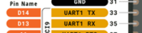
Hi @momokash. You got it right. Using the Serial1 object in your sketch will cause communication on UART1 (Arduino pins 13 and 14) on the Portenta C33 board.
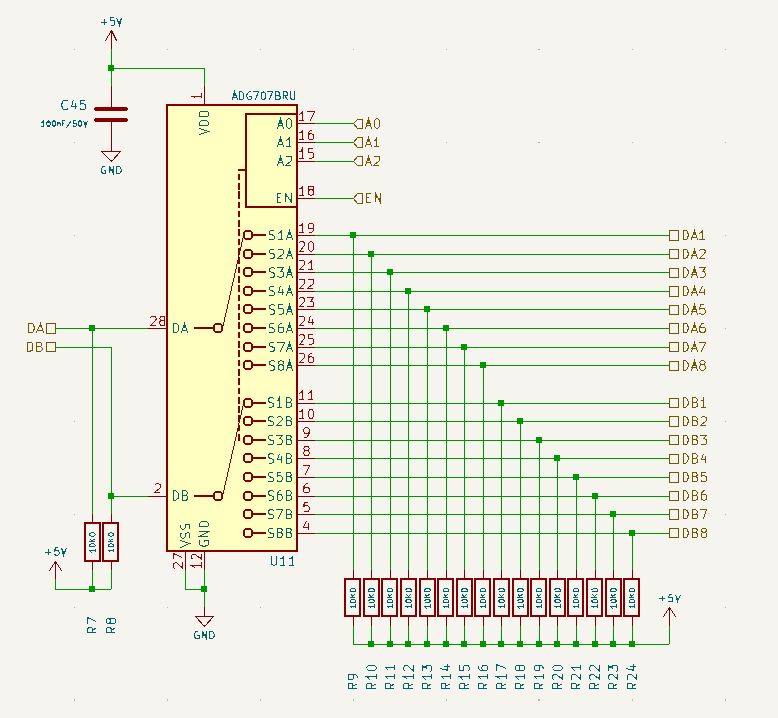
I have a pcb board that have the UART0 (its on the high densitiy connector, pins 49 and 50) to a multiplexer to read 8 different ultrasonic sensors
My issue is that the multiplexer seems to be not working, here is the code im testing and also the schematics of the circuit
#include <Arduino.h>
// Multiplexer control pins
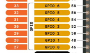
const int enPin = 31; // asw_EN
const int a0Pin = 30; // asw_A0
const int a1Pin = 29; // asw_A1
const int a2Pin = 28; // asw_A2
void setup() {
// Initialize multiplexer control pins
pinMode(enPin, OUTPUT);
pinMode(a0Pin, OUTPUT);
pinMode(a1Pin, OUTPUT);
pinMode(a2Pin, OUTPUT);
// Initialize serial communication for monitoring
Serial.begin(9600);
Serial1.begin(9600); // UART for the ultrasonic sensor
// Test message
Serial.println("Starting UART test with hardware UART...");
// Enable multiplexer
digitalWrite(enPin, LOW); // Make sure to enable the multiplexer
}
void loop() {
// Test each multiplexer combination
for (int i = 0; i < 8; i++) {
// Configure multiplexer pins according to the combination
digitalWrite(a0Pin, i & 0x01);
digitalWrite(a1Pin, (i >> 1) & 0x01);
digitalWrite(a2Pin, (i >> 2) & 0x01);
// Debug message
Serial.print("Multiplexer pin configuration: A0=");
Serial.print(digitalRead(a0Pin));
Serial.print(", A1=");
Serial.print(digitalRead(a1Pin));
Serial.print(", A2=");
Serial.println(digitalRead(a2Pin));
// Send the necessary command to the sensor
Serial1.write(0x01); // Send byte 0x01 to activate the sensor
Serial.print("Sending 0x01 in combination: ");
Serial.println(i, BIN);
// Wait a moment for the reading
delay(100);
// Read the sensor's response
if (Serial1.available() > 0) {
Serial.print("Data received in combination ");
Serial.print(i, BIN);
Serial.print(": ");
while (Serial1.available() > 0) {
int reading = Serial1.read();
Serial.print(reading, HEX);
Serial.print(" ");
}
Serial.println();
} else {
Serial.print("No data received in combination ");
Serial.println(i, BIN);
}
// Wait a second before the next reading
delay(1000);
}
}
The ultrasonic are UART controlled, so they need to receive a "1" to work, but my issue is that no matter the code or the serial i choose the rx and tx pins are always 5v (as they have pull up resistors) but i cant make this multiplexer work
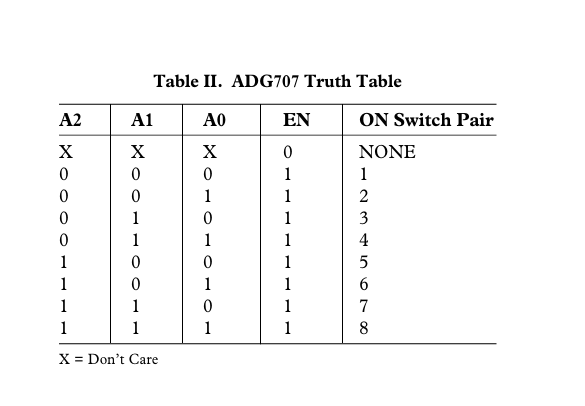
However i still cant make this work so the sensor when i connect it to the da1 and db1 is still not communicating, the multiplexer truth table is this
In my code im doing this
#include <Arduino.h>
          #define UART2_TX_PIN        49
          #define UART2_RX_PIN        50
// Multiplexer control pins
const int enPin = 31; // asw_EN
const int a0Pin = 30; // asw_A0
const int a1Pin = 29; // asw_A1
const int a2Pin = 28; // asw_A2
void setup() {
// Initialize multiplexer control pins
pinMode(enPin, OUTPUT);
pinMode(a0Pin, OUTPUT);
pinMode(a1Pin, OUTPUT);
pinMode(a2Pin, OUTPUT);
// Initialize serial communication for monitoring
Serial.begin(9600);
Serial2.begin(9600); // UART for the ultrasonic sensor
// Test message
Serial.println("Starting UART test with hardware UART...");
Serial.println("Multiplexer configured to use DA1 and DB1.");
}
void loop() {
// Enable multiplexer and select the first channel (DA1 and DB1)
digitalWrite(enPin, HIGH); // Enable multiplexer
digitalWrite(a0Pin, LOW);
digitalWrite(a1Pin, LOW);
digitalWrite(a2Pin, LOW);
// Send the necessary command to the sensor
Serial1.write(0x01); // Send byte 0x01 to activate the sensor
Serial.println("Sending 0x01 to sensor on DA1 and DB1.");
// Wait a moment for the reading
delay(100);
// Read the sensor's response
  if (Serial1.available() > 0) {
    Serial.print("Data received: ");
    while (Serial1.available() > 0) {
      int reading = Serial1.read();
Serial.print(reading, HEX);
Serial.print(" ");
}
Serial.println();
} else {
Serial.println("No data received.");
}
// Wait a second before the next reading
delay(1000);
}
Is there something wrong that im doing here ?
im declarating the pins with those values following the schematics of the portenta c33
You wrote Serial1 instead of Serial2 in these lines. Change it to Serial2 and then upload the updated sketch to your board. Hopefully it will start working as expected after that.
Hi, so i saw the mistake and correct it, still nothing i cant even here the ultrasonic sensor sending signals, which gave tells me that even the line sending a 1 to the ultrasonic is not working
I changed the focus and im using software serial
#include <Arduino.h>
#include <SoftwareSerial.h>

#define UART2_TX_PIN 50
#define UART2_RX_PIN 49

// Multiplexer control pins
const int enPin = 31; // asw_EN
const int a0Pin = 30; // asw_A0
const int a1Pin = 29; // asw_A1
const int a2Pin = 28; // asw_A2

// Initialize SoftwareSerial
SoftwareSerial sensorSerial(UART2_RX_PIN, UART2_TX_PIN);

void setup() {
  // Initialize multiplexer control pins
  pinMode(enPin, OUTPUT);
  pinMode(a0Pin, OUTPUT);
  pinMode(a1Pin, OUTPUT);
  pinMode(a2Pin, OUTPUT);

  // Initialize serial communication for monitoring
  Serial.begin(9600);
  sensorSerial.begin(115200); // UART for the ultrasonic sensor

  // Test message
  Serial.println("Starting UART test with SoftwareSerial...");

  Serial.println("Multiplexer configured to use DA1 and DB1.");
}

void loop() {
  // Enable multiplexer and select the first channel (DA1 and DB1)
  digitalWrite(enPin, HIGH); // Enable multiplexer
  digitalWrite(a0Pin, LOW);
  digitalWrite(a1Pin, LOW);
  digitalWrite(a2Pin, LOW);

  // Debugging: Check the state of the multiplexer pins
  Serial.print("EN: "); Serial.println(digitalRead(enPin));
  Serial.print("A0: "); Serial.println(digitalRead(a0Pin));
  Serial.print("A1: "); Serial.println(digitalRead(a1Pin));
  Serial.print("A2: "); Serial.println(digitalRead(a2Pin));

  // Send the necessary command to the sensor
  sensorSerial.write(0x01); // Send byte 0x01 to activate the sensor
  Serial.println("Sending 0x01 to sensor on DA1 and DB1.");

  // Wait a moment for the reading
  delay(300); //

  // Read the sensor's response directly
  Serial.print("Data received: ");
  long startTime = millis();
  while (millis() - startTime < 1000) { // Read for 1 second
    if (sensorSerial.available()) {
      int reading = sensorSerial.read();
      Serial.print(reading, HEX);
      Serial.print(" ");
    }
  }
  Serial.println();

  // Wait a second before the next reading
  delay(1000);
}
This actually makes the ultrasonic work, i can here the sound of it, but im not able to read anything from it, i feel this is a code issue because i even selected the pin2 and 3 to test if it was a multiplexer issue and also no readings
Pin 49 is the TX pin for Serial2 and pin 50 is the RX pin for Serial2. The fact that you are using for the opposite signals in your SoftwareSerial code indicates you might have the pins swapped for the purposes of use with Serial2 in your wiring between the Portenta C33 and the multiplexer.
Hi so i change that on purpose, but your message gave me an insight, it was no the pcb, it was a connection that was mixed in the US i corrected and now works fine
here is my code
#include <Arduino.h>

#define UART2_TX_PIN 49
#define UART2_RX_PIN 50

// Multiplexer control pins
const int enPin = 31; // asw_EN
const int a0Pin = 30; // asw_A0
const int a1Pin = 29; // asw_A1
const int a2Pin = 28; // asw_A2

void setup() {
  // Initialize multiplexer control pins
  pinMode(enPin, OUTPUT);
  pinMode(a0Pin, OUTPUT);
  pinMode(a1Pin, OUTPUT);
  pinMode(a2Pin, OUTPUT);

  // Initialize serial communication for monitoring
  Serial.begin(9600);
  Serial2.begin(9600); // UART for the ultrasonic sensor

  // Test message
  Serial.println("Starting UART test with hardware UART...");
  Serial.println("Multiplexer configured to use DA1 and DB1.");
}

void loop() {
  // Enable multiplexer and select the first channel (DA1 and DB1)
  digitalWrite(enPin, HIGH); // Enable multiplexer
  digitalWrite(a0Pin, HIGH);
  digitalWrite(a1Pin, HIGH);
  digitalWrite(a2Pin, LOW);

  // Send the necessary command to the sensor
  Serial2.write(0x01); // Send byte 0x01 to activate the sensor
  Serial.println("Sending 0x01 to sensor on DA1 and DB1.");

  // Wait a moment for the reading
  delay(100);

  // Read the sensor's response
  if (Serial2.available() > 0) {
    Serial.print("Data received: ");
    uint8_t data[4];
    int index = 0;
    while (Serial2.available() > 0 && index < 4) {
      data[index++] = Serial2.read();
    }

    // Print raw data for debugging
    for (int i = 0; i < index; i++) {
      Serial.print(data[i], HEX);
      Serial.print(" ");
    }
    Serial.println();

    // Check for valid data
    if (index == 4 && data[0] == 0xFF) {
      uint16_t distance = (data[1] << 8) + data[2];
      Serial.print("Distance: ");
      Serial.print(distance);
      Serial.println(" mm");
    } else {
      Serial.println("Invalid data received.");
    }
  } else {
    Serial.println("No data received.");
  }

  // Wait a second before the next reading
  delay(1000);
}

Thanks for the help!