Dear all,
I am facing problems dimming the background light on my display and need guidance in finding the root-cause. Maybe you have some insights that can help me directing my efforts or have faced similar issues...
Problem formulation: I bought the GC9A01A 1"28 240x240 RGB DC3.3V round LCD display from DONGKER (Amazonlink) with the assumption that the BLK input on the display simply could be connected to a PWM IO pin on my Atmega328p AU (Arduino pin 9 / PB1) and by using the analogWrite() I would be able to adjust the duty cycle to dim the background lights of the display ("X/255"). However, when testing with different values, even as low as <10, I am not able to visually see any difference on my display. NB: the display is working as intended in other matters and I am able to get it to start and show the text I want.
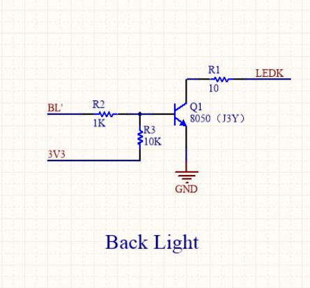
I am unable to find the schematics and datasheet for the specific product by DONGKER which of course is problematic, instead I refer to the Waveshare datasheet for the data sheet and Waveshare schematics to get an understanding of what should be included for it to work. The latter (schematics) not being the same as my product when comparing to the product (see picture in previous Amazon link), which is one of hypotheses as to why it will not work... more on that later.
After searching the web for help I still find myself struggling. I have some thoughts down below since I am fairly new to this, I do not know where to start. Please advice.
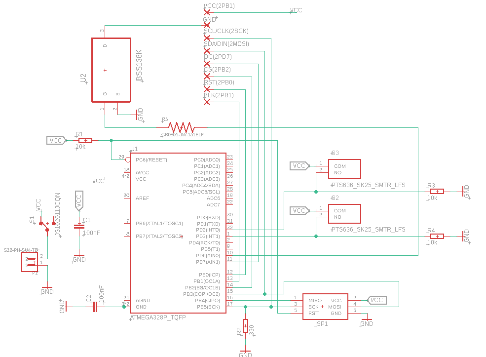
Background info: I am running the Atmega328p AU (and display) on roughly 3.3Volts @8MHz using the internal oscillator (no external clock). Power source is a Li-Po battery 3.7Volt. For programing I am using Arduino and as for the libraries to control the display I am using Adafruit_GC9A01A.h found on Githubjointly with SPI.h and Adafruit_GFX.h.
Schematics:
Hyptheses:
-
My product lacks the appropriate components to enable dimming of backlight connecting only the PWM-pin to BLK. To make it work I would need to mirror the schematics shown in picture below (copied from WaveShare schematics linked above) on my PCB where BL in the picture would be connected to the PWM-pin, 3V3 to my battery, and LEDK to BLK on the display. The three resistors as well as the (I assume MOSFET) would then need to go on my PCB.
-
My screen has the appropriate components but I need to program the display to enable the dimming function and backlight control.
-
The display should be working simply by attaching PWM to the BLK but has manufacturing faults and I should get a new one.
What I want to achieve and why: I am working on a project where I need an affordable, low energy consuming, portable timer with a display and one step in this is to reduce the brightness of my display to decrease energy consumption and ease the stress on my battery. From a design point of view, the round shape is highly favourable.
/Many thanks in advance
Markus