Could you try this?
void loop()
{
  for(int x = 0; x < 8; x++)
  {
    for (int i=0; i<64; i++)
    {
      sendData(i, 1 << x);
    }
    delay(1000);
    Clear();
    delay(100);
  }
}Could you try this?
void loop()
{
for(int x = 0; x < 8; x++)
{
for (int i=0; i<64; i++)
{
sendData(i, 1 << x);
}
delay(1000);
Clear();
delay(100);
}
}
    uint8_t adr[64] =
    {
      0b000000,0b000001,0b000010,0b000011,
...
      0b111100,0b111101,0b111110,0b111111
      };


sendData(adr[1],...);
This seems to be a quite complicate way to say
sendData(1,...);but lookup tables come handy when you want to translate a number to a segment pattern:
sendData(...,seg[1]);I try your code and it is opening sometimes 1seg sometimes 2seg at once, for all 3digits consecutively, and very randomly like it was in my first tries.
Look on my code I provided earlier because it is tested and working.
I didnt clean it up, since I loop into more bits than necessary, but it is showing my line of thought very clearly. Cleaning it up is very easy after this. So try to automate my brute code. I will post the clean code next.
Ok... a quite high level view on this.
You have a book.
Each page of the book has 4 boxes labeled COM0 to COM3.
Since you only connected SEG0 to SEG5 you only need 6 pages (page 0 - 5)
With void sendData(uint8_t address, uint8_t value) you can write to the book.
address is the page number and value ticks the boxes.
The value 1 ticks the box COM0.
The value 2 ticks the box COM1.
The value 4 ticks the box COM2.
The value 8 ticks the box COM3.
You can sum up stuff. 5 ticks COM0 and COM2.
Now the controller reads through the pages.
For Page x it copys the boxes to the output COM0 to COM3 and it activates SEGx.
Now your LCD is wired as a matrix. Each segment is connected to one COMx and one SEGx.
When both output high, the segment turns on.
Depending on your wiring, this might light up every segment one after another on one digit:
Clear();
sendData( 0 , 1); delay(1000);
sendData( 0 , 2); delay(1000);
sendData( 0 , 4); delay(1000);
sendData( 0 , 8); delay(1000);

sendData( 0 , 0);
sendData( 1 , 1); delay(1000);
sendData( 1 , 2); delay(1000);
sendData( 1 , 4); delay(1000);
sendData( 1 , 8); delay(1000);This is the functional block of code that will cycle through each segment of each digit, starting with digit1 then 2 then3 and then again from 1.
This code is cleaned to open each segment one after another, not like before when it was incrementing into unused bits of the IC. Now is right on the segment.
It is tested and working fine.
We have to add a Clear() after the end of each addr block, because it's last segment will remain ON if not cleared. We can clear it using specific Clear code: for adr0 we can use
sendData(adr[0],seg[0]); // instead of Clear();
and this way, will make it more faster, but is custom reset in this case.
Im lazy and Im using that Clear() function for the moment but what I said is part of program efficiency that is done when you make the final code.
For all these test code's we can use some inefficiencies, no one will die.
  void CycleSegmentsForDigit1()
  {
      sendData(adr[0],seg[1]); delay(200);
      sendData(adr[0],seg[2]); delay(200);
      sendData(adr[0],seg[3]); delay(200);
      Clear();
      sendData(adr[1],seg[1]); delay(200);
      sendData(adr[1],seg[2]); delay(200);
      sendData(adr[1],seg[3]); delay(200);
      sendData(adr[1],seg[4]); delay(200);
      Clear();delay(500);
  }
  void CycleSegmentsForDigit2()
  {
      sendData(adr[2],seg[1]); delay(200);
      sendData(adr[2],seg[2]); delay(200);
      sendData(adr[2],seg[3]); delay(200);
      Clear();
      sendData(adr[3],seg[1]); delay(200);
      sendData(adr[3],seg[2]); delay(200);
      sendData(adr[3],seg[3]); delay(200);
      sendData(adr[3],seg[4]); delay(200);
      Clear();delay(500);
  }
  void CycleSegmentsForDigit3()
  {
      sendData(adr[4],seg[1]); delay(200);
      sendData(adr[4],seg[2]); delay(200);
      sendData(adr[4],seg[3]); delay(200);
      Clear();
      sendData(adr[5],seg[1]); delay(200);
      sendData(adr[5],seg[2]); delay(200);
      sendData(adr[5],seg[3]); delay(200);
      sendData(adr[5],seg[4]); delay(200);
      Clear();delay(500);
  }
  void setup()
  {
   config();
   Clear();
  }


  void loop()
  {
    CycleSegmentsForDigit1();
    CycleSegmentsForDigit2();
    CycleSegmentsForDigit3();
  }
YES ! Your code is simpler than mine !!!
And is working the same as mine !
Here is the cleaned up and tested version of your code:
 void RintinCode()
    {
      sendData( 0 , 1); delay(1000);
      sendData( 0 , 2); delay(1000);
      sendData( 0 , 4); delay(1000); //this last bit will remain open if not Cleared!!!
      Clear();
      sendData( 1 , 1); delay(1000);
      sendData( 1 , 2); delay(1000);
      sendData( 1 , 4); delay(1000);
      sendData( 1 , 8); delay(1000); //this last bit will remain open if not Cleared!!!
      Clear();
    }
VERY interesting code !!! I like it.
How this ( 1 , 8); translates into my binary?
Remember, that your 8 is my 0b01000000
    uint8_t seg[8] =
    {
      0b00000000,0b00000001,0b00000010,0b00000100,
      0b00001000,0b00010000,0b00100000,0b01000000
    };
Very strange code !!! First time seeing something like this.
But cool ! I like it because its very simple...a bit cryptic though.
8 decimal translates to 0b00001000. (1, 8) -> (1,seg[4])
I think this codes goes through all segments one after another on every segment:
void RintinCode(uint8_t x)
    {
      sendData( 0+x , 1); delay(1000);
      sendData( 0+x , 2); delay(1000);
      sendData( 0+x , 4); delay(1000); //this last bit will remain open if not Cleared!!!
      Clear();
      sendData( 1+x , 1); delay(1000);
      sendData( 1+x , 2); delay(1000);
      sendData( 1+x , 4); delay(1000);
      sendData( 1+x , 8); delay(1000); //this last bit will remain open if not Cleared!!!
      Clear();
    }


RintinCode(0);
RintinCode(2);
RintinCode(4);
I think now is the time to create a lookup table for number -> segment pattern.
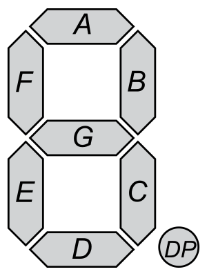
What do you need to call to light up segment A (B,C,...,G)?
yes, until now I just leave it to light up whatever segments, but the order is not right.
My LCD does not have that DP point. Only 7seg digits x3
Here is the Segment order:
      sendData(adr[0],seg[1]); delay(t);    //a
      sendData(adr[0],seg[2]); delay(t);    //b
      sendData(adr[0],seg[3]); delay(t);    //c
      Clear();
      sendData(adr[1],seg[1]); delay(t);    //f
      sendData(adr[1],seg[2]); delay(t);    //g
      sendData(adr[1],seg[3]); delay(t);    //e
      sendData(adr[1],seg[4]); delay(t);    //d


so the order will be:
      sendData(adr[0],seg[1]); delay(t);    //a
      sendData(adr[0],seg[2]); delay(t);    //b
      sendData(adr[0],seg[3]); delay(t);    //c
      Clear();
      sendData(adr[1],seg[4]); delay(t);    //d
      sendData(adr[1],seg[3]); delay(t);    //e
      sendData(adr[1],seg[1]); delay(t);    //f
      sendData(adr[1],seg[2]); delay(t);    //g
I tested your last code and indeed it is doing the right thing. It is working very nice.
I think your void RintinCode(uint8_t x) can contain only a simple int.
Now you need to fill out all those x'es and it should display 012
uint8_t LutEven[10] =
{
  //   CBA
    0b0111, // 0
    0b0110, // 1
    0b0xxx, // 2
    0b0xxx, // 3
    0b0xxx, // 4
    0b0xxx, // 5
    0b0xxx, // 6
    0b0xxx, // 7
    0b0xxx, // 8
    0b0xxx, // 9
};

uint8_t LutOdd[10] =
{
  //  DEGF
    0b1101, // 0
    0b0000, // 1
    0bxxxx, // 2
    0bxxxx, // 3
    0bxxxx, // 4
    0bxxxx, // 5
    0bxxxx, // 6
    0bxxxx, // 7
    0bxxxx, // 8
    0bxxxx, // 9
};

sendData(0, LutEven[0]);
sendData(1, LutOdd[0]);

sendData(2, LutEven[1]);
sendData(3, LutOdd[1]);

sendData(4, LutEven[2]);
sendData(5, LutOdd[2]);
so, check this out. My original seg[8] is the original used code.
I made a new binary one named segx[9] (to accommodate the last bit)
Then I modified only my CycleSegmentsForDigit1 function. And I get sometimes 1segment, sometimes 2segments open. Using this code:
    uint8_t seg[8] = //locative (bit location)
    {
      0b00000000,0b00000001,0b00000010,0b00000100,
      0b00001000,0b00010000,0b00100000,0b01000000
    };
    uint8_t segx[9] = //binary
    {
      0b00000000,0b00000001,0b00000010,0b00000011,
      0b00000100,0b00000101,0b00000110,0b00000111,
      0b00001000,
    };
  void CycleSegmentsForDigit1()
  {
      sendData(adr[0],segx[1]); delay(t);    //a
      sendData(adr[0],segx[2]); delay(t);    //b
      sendData(adr[0],segx[3]); delay(t);    //c
      Clear();
      sendData(adr[1],segx[1]); delay(t);    //f
      sendData(adr[1],segx[2]); delay(t);    //g
      sendData(adr[1],segx[3]); delay(t);    //e
      sendData(adr[1],segx[4]); delay(t);    //d
      Clear();delay(500);
  }
BUT
I remember that you jumped in binary in your code
sendData( 0 , 1);
sendData( 0 , 2);
sendData( 0 , 4);
sendData( 0 , 8);
and I modify it on mine as well:
  void CycleSegmentsForDigit1()
  {
      sendData(adr[0],segx[1]); delay(t);    //a
      sendData(adr[0],segx[2]); delay(t);    //b
      sendData(adr[0],segx[4]); delay(t);    //c
      Clear();
      sendData(adr[1],segx[1]); delay(t);    //f
      sendData(adr[1],segx[2]); delay(t);    //g
      sendData(adr[1],segx[4]); delay(t);    //e
      sendData(adr[1],segx[8]); delay(t);    //d
      Clear();delay(500);
  }
And now... is doing the right thing ! WOW
I wanted to understand what did your code did.
Very interesting !!! This was only for me to get it.
I will revert everything back as it was.
I filled up the xxx'es but is showing gibberish
Maybe I filled them wrong?
I filled them binary but from 0000, //8 towards 0b0111, // 1
so if you read from the bottom towards the top you will read binary incrementation.
    uint8_t LutEven[10] =
    {
      //   CBA
        0b0111, // 1
        0b0110, // 2
        0b0101, // 3
        0b0100, // 4
        0b0011, // 5
        0b0010, // 6
        0b0001, // 7
        0b0000, // 8
    };
    uint8_t LutOdd[10] =
    {
      //  DEGF
        0b1111, // 1
        0b1110, // 2
        0b1101, // 3
        0b1100, // 4
        0b1011, // 5
        0b1010, // 6
        0b1001, // 7
        0b1000, // 8
    };
3 light up segments A,B,C,D,G
this would translate into
      //   CBA
        0b0111, // 3

      //  DEGF
        0b1010, // 3
I do not understand
Fill up those LUT arrays because I dont know what you are thinking to.
I filled them binary but from 0b0000, //8 towards 0b0111, // 1
so if you read from the bottom towards the top you will read binary incrementation.
Did i mention that I'm lazy?
Here is how it goes.
This a a look up table for the x's bit set (ignoring the offset here)
This is a lookup table for a == segx[a] or in other words: You have written the same thing in a different representation.
And here is the relation to the COMx ports on the LCD driver and the value:
COM0 -> 1 -> 0b0001
COM1 -> 2 -> 0b0010
COM2 -> 4 -> 0b0100
COM3 -> 8 -> 0b1000
When you are writing 5 these COMx are selected:
 5 -> 0b0101
      0b0001 -> COM0
      0b0100 -> COM2
Im making a visual 'map' of everything we did so far.
...
A better Clear function:
    void Clear()
    {
      for(uint8_t x=0; x<6; x++)  //Im using only (0-5) 6 addr for this 3digit LCD
      sendData(adr[x],seg[0]);    //set to 0 each addr clearing the LCD segments
    }
Thats great.
So now to display a 3 we need to turn the segments ABCDG on
From previous experiments we know how to turn on single segments.
This should give us a flickering 3:
while(1)
{
      sendData(adr[0],seg[1]); delay(t);    //a
      sendData(adr[0],seg[2]); delay(t);    //b
      sendData(adr[0],seg[3]); delay(t);    //c
      sendData(adr[1],seg[2]); delay(t);    //g
      sendData(adr[1],seg[4]); delay(t);    //d
}
but we can combine all segments and write to them only once:
uint8_t even = seg[1] + seg[2] + seg[3];
uint8_t odd = seg[2] + seg[4];
sendData(0,even);
sendData(1,odd);is working, BUT ... the 'even' code is diluting the intensity of this 3.
The more contrast is on the 'odd' code.
hmmmmmm - big problem !
I believe we need to send all these bits (or byte) all at once.
Like we did with a single bit per address for a single segment.
Is my idea... but at this part, I suck. Im not good anymore.
I told you: Im good but not THAT good.
