- Im trying to figure out how to drive (manually-bitbang) a HT1621B LCD driver IC. It is capable of driving multiplexed LCDs. They are very cheap, but only in smd form, which is a bit of a challenge to solder all its tiny 48 pins. See youtu.be/xwRXpbxjLcw - you can skip through the movie since it's a long one. I actually managed to drive them using a special library in arduino, and they work beautifully but...I want manual drive. Why? because I can use only logic ICs like nand gates,multiplexers, FF's, etc 40 and 74 series, and also my favorite very easy to drive 12F508 PIC, and why not even an EEPROM. And I can also add custom characters or shapes or symbols.
- I read their datasheet a couple of times and STILL, I can not decipher the real way of driving them. I also find 2 AN's (AppNotes) AN2343-Cypress and AN0468e HT162x Application Guidelines -HOLTEK. They helped a little but not completely.
- Here is a list with all my LCD movies I made so far: https://www.youtube.com/playlist?list=PL6NJF1kQFOAI0-AstwH5YHuOHenjLtkbS, including this HT1621B IC. Again, skip through their content since Im showing you what I tried and how high I could reach.
Thank you very much.
HT1621B - HCTSEMI -multiplexed LCD Driver smd.pdf (305.5 KB)
AN0468e HT162x Application Guidelines -HOLTEK.pdf (860.7 KB)
AN2343-Cypress.pdf (300.0 KB)
Did you not think that the "Displays" forum category would be a more suitable place to post your topic?
I will move it for you. Please consider more carefully where you post in future.
1 Like
please post the pdf here, as it is not available without registration
1 Like
Im bitbanging using arduino uno R3 board, with direct wire links to the IC pins.
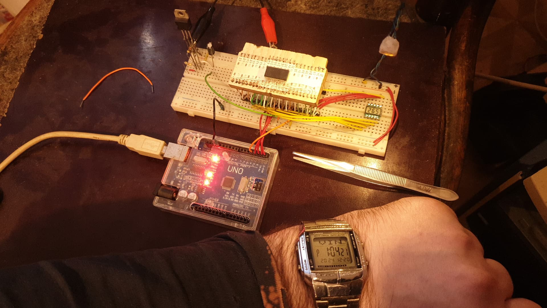
So this is a working setup, that is using
lcd.begin(0, 2, 3); // (cs=0, wr=2, Data=3)
where, cs=0 means that IC cs pin is linked to pin0 on arduino. , The same logic applies for the other pins in the arduino code + library.
Im using a test program to reassure everything is connected and working correctly.
Next is to actually find a way to bitbang this IC input pins. Those 3 mentioned.
If it helps, these are the 5 wire links in the image:
//HT1621B pin = Arduino pin
//cs=0, wr=2, dt=3, rd=1,irq=4
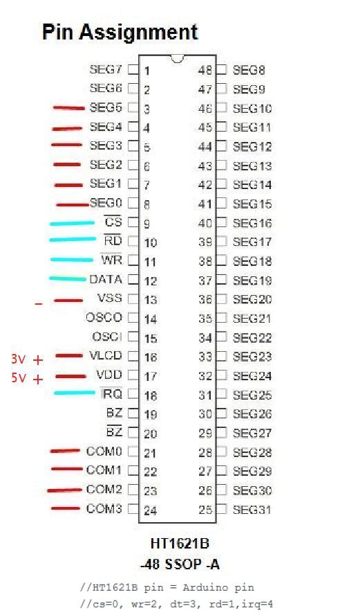
The red links in the image, were the easy wiring I made the first thing after I soldered the IC.
The harder links are the cyan ones that needs programming data.
This is the test program that worked perfectly with what I have here.
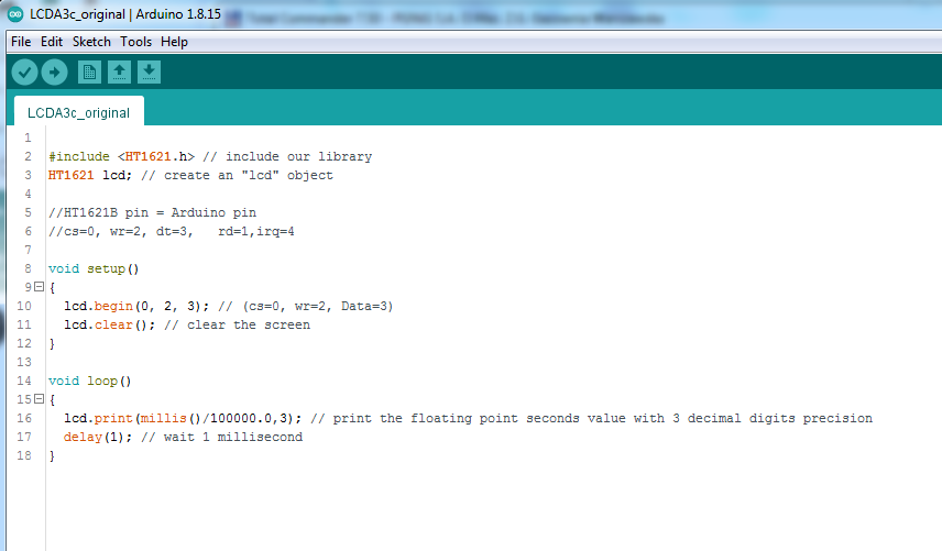
LCDA3c_original.ino
(420 Bytes)
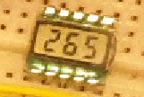
This program is counting from 0-999 on that little multiplexed 3 digit LCD and restart, so counting to infinite. Its a test program.
This program is assuring (us) me that I connected everything correctly, because it is working.
The next step is to find a way to bitbang those 3 pins.
I actually tried to crack this HT1621.h library and another 2 made for driving this IC.
I failed and I stopped everything for ~1year.
Now Im trying again.
So to be absolutely clear,
1- Im using a test program now, to make it crystal clear that all the wiring are correct, because the LCD is working fine.
2- What I actually plan is to bitbang those 3 HT1621B pins [cs, wr, dt] and make it work as it was from the library itself. That's my target.
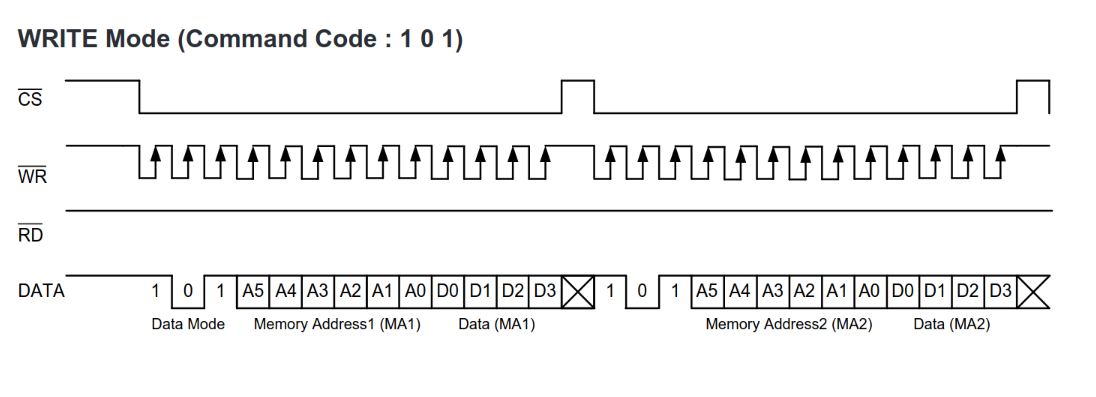
For writing data to the display you follow this timing diagram:
For commands this looks like this:

As code it might look like this:
    void shiftOutBits(int count, uint16_t value){
      for (int x = count; x > 0; x--) {
        bool val = (bit(x - 1) & value) != 0;
        digitalWrite(_pin_wr, LOW);
        digitalWrite(_pin_data, val);
        digitalWrite(_pin_wr, HIGH);
      }
    }

    void sendCommand(uint16_t cmd){
      digitalWrite(_pin_cs, LOW);
      shiftOutBits(3, 0b100);
      shiftOutBits(9, cmd);
      digitalWrite(_pin_cs, HIGH);
    }

    void sendData4(uint8_t address, uint8_t value){
      digitalWrite(_pin_cs, LOW);
      shiftOutBits(3, 0b101);
      shiftOutBits(6, address);
      shiftOutBits(4, value);
      digitalWrite(_pin_cs, HIGH);
    }
The initialization for the LCD I steal from my library
  sendCommand(0b001010010); // Bias 1/3, 10/4 commons
  sendCommand(0b000110000); // Internal RC 256K
  sendCommand(0b000001010); // Disable WDT
  sendCommand(0b000001000); // Disable time base output
  sendCommand(0b000000010); // Turn on system oscillator
  sendCommand(0b000000110); // LCD on
1 Like
Thank you @Rintin !
I manage to put something together after your suggestion.
Here is the full code I used:
//HT1621B pin = Arduino pin
//cs=0, wr=2, dt=3,  rd=1,irq=4
  int _pin_cs=0;
  int _pin_wr=2;
  int _pin_data=3;

    void shiftOutBits(int count, uint16_t value){
      for (int x = count; x > 0; x--)
      {
        bool val = (bit(x - 1) & value) != 0;
        digitalWrite(_pin_wr, LOW);
        digitalWrite(_pin_data, val);
        digitalWrite(_pin_wr, HIGH);
      }
    }

    void sendCommand(uint16_t cmd)
    {
      digitalWrite(_pin_cs, LOW);
      shiftOutBits(3, 0b100);
      shiftOutBits(9, cmd);
      digitalWrite(_pin_cs, HIGH);
    }


    void config()
    {
      pinMode(_pin_cs, OUTPUT);
      pinMode(_pin_wr, OUTPUT);
      pinMode(_pin_data, OUTPUT);
      sendCommand(0b001010010);   // Bias 1/3, 4com       0b0 0101 0010
      sendCommand(0b000110000);   // Internal RC 256K
      sendCommand(0b000001010);   // Disable WDT
      sendCommand(0b000001000);   // Disable time base output
      sendCommand(0b000000010);   // Turn on system oscillator
      sendCommand(0b000000110);   // LCD on
    }

    void sendData(uint8_t address, uint8_t value)
    {
      digitalWrite(_pin_cs, LOW);
      shiftOutBits(3, 0b101);
      shiftOutBits(6, address);
      shiftOutBits(4, value);
      digitalWrite(_pin_cs, HIGH);
    }

    void Clear()
    {
      for(uint8_t adr=0; adr<111111; adr++)
      {
        sendData(adr,0000);
      }
    }


    void Execute()
    {
      for(uint8_t adr=0; adr<111111; adr++)
      {
        sendData(adr,0010);
      }
    }

  void setup()
  {
   config();
   Clear();

   //Execute();
  }
  void loop()
  {

  }
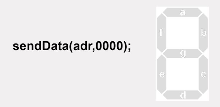
The Clear() is clearing the LCD successfully.
But...
Execute() (afterClear() ) is not changing any segment, and I comment it out.
So I got back to Clear() and modify
its data bits at this line: sendData(adr,0000);
so I changed those 4 bits and I obtained this effect for all 3LCD digits in the same time. This is ok, since Im not aware yet, which range of addr is for digit 1,2 and 3 of my LCD.

sendData(adr,0111); does nothing, no effect.
Im still very confused how this works.
But it is giving signs of working, which is a very good thing; thanks to @Rintin.
I also find this, most probably complete, full set of Settings :
#define  BIAS     0b100001010010     //0b1000 0101 0010  1/3duty 4com
#define  SYSDIS   0b100000000000     //0b1000 0000 0000  Off Oscillator and LCD Bias Generator
#define  SYSEN    0b100000000010     //0b1000 0000 0010  Turn on system oscillator
#define  LCDOFF   0b100000000100     //0b1000 0000 0100  Off LCD bias
#define  LCDON    0b100000000110     //0b1000 0000 0110  Turn on LCD bias
#define  XTAL     0b100000101000     //0b1000 0010 1000  External clock
#define  RC256    0b100000110000     //0b1000 0011 0000  internal clock
#define  TONEON   0b100000010010     //0b1000 0001 0010  Turn on sound output
#define  TONEOFF  0b100000010000     //0b1000 0001 0000  Turn off sound output
#define  WDTDIS   0b100000001010     //0b1000 0000 1010  disable watchdog
But your list might be better, because is cleaned of unnecessary instructions.
I put this here just as a reference.
The datasheet should contain a full list of the commands
https://www.holtek.com/webapi/116711/HT1621v330.pdf (Look for Command Summary)
Your list does include the operation prefix while my sendCommand() expects it without.
CS and WR are low active, idle high.
You need to call digitalWrite(..., HIGH); after setting the pinMode().
You are writing in binary. Please tell the compiler that you are writing in binary when you are writing in binary by adding 0b in front of the number (0b111111).
Please also check your sendData(...) calls for this.
Pin 0 and pin 1 on an Arduino Uno R3 are shared with the USB port. Maybe change this pin.
1 Like
should I put 10k pullup res on these 2 pins? Right now they are direct wired.
probably like this:
void config()
{
      pinMode(_pin_cs, OUTPUT);
      pinMode(_pin_wr, OUTPUT);
pinMode(_pin_data, OUTPUT);
digitalWrite(_pin_cs, HIGH);
digitalWrite(_pin_wr, HIGH);
digitalWrite(_pin_data, HIGH);
sendCommand(0b001010010); // Bias 1/3, 4com 0b0 0101 0010
sendCommand(0b000110000); // Internal RC 256K
sendCommand(0b000001010); // Disable WDT
sendCommand(0b000001000); // Disable time base output
sendCommand(0b000000010); // Turn on system oscillator
sendCommand(0b000000110); // LCD on
}
I missed that. Im more used to program in C# than in low level.
How do I even make a for loop to search in binary? My only thought is to write down every possible permutation in a list and then loop through that list. Or array. But is a lot of writing. Im not very good with the shift operator, Im aware of it, but I never understand it fully. Im good but not THAT good.
Thank you for your very nice suggestions. I will try my best.
The pin is configured as push-pull output. A pullup resistor would only define the level before setup() is called. I don't see the need here.
How would you normally do this?
I change them as
//HT1621B pin = Arduino pin
//dt=2, wr=3,rd=4, cs=5,    ,irq=6
  int _pin_data=2;
  int _pin_wr=3;
  int _pin_cs=5;
It was a good idea to put back the test program to check the wiring and the code.
Now is checked and working with this new wiring.
like I showed you, in any other type than binary.
this is what I already started to make
I made this test code:
    uint8_t bit1=0001;
    void Execute()
    {
      sendData(000000,bit1); delay(100);
      sendData(000001,bit1); delay(100);
      sendData(000010,bit1); delay(100);
      sendData(000011,bit1); delay(100);
      sendData(000100,bit1); delay(100);
      sendData(000101,bit1); delay(100);
      sendData(000110,bit1); delay(100);
      sendData(000110,bit1); delay(100);
      sendData(000111,bit1); delay(100);
    }

  void setup()
  {
   config();
   Clear();

  }
  void loop()
  {
    Execute();
  }
and the LCD is blank.
    uint8_t adr[64] =
    {
      000000,000001,000010,000011,
      000100,000101,000110,000111,
      001000,001001,001010,001011,
      001100,001101,001110,001111,
      010000,010001,010010,010011,
      010100,010101,010110,010111,
      011000,011001,011010,011011,
      011100,011101,011110,011111,
      100000,100001,100010,100011,
      100100,100101,100110,100111,
      101000,101001,101010,101011,
      101100,101101,101110,101111,
      110000,110001,110010,110011,
      110100,110101,110110,110111,
      111000,111001,111010,111011,
      111100,111101,111110,111111
      };
  void setup()
  {
   config();
   //Clear();

  }
  void loop()
  {
    for (int i=0; i<64; i++)
    sendData(adr[i],0001); delay(100);
  }
I avoid to add that Clear(), because after it, nothing works.
Clearly I dont know how to clear it properly.
And even if its clearing the LCD, it is clearing something else that is not allowing any other code execution after it.
The code I made here is looping now, and is opening the same segments as before.
You are counting in octal.
000111 (octal, leading zero) = 73 (decimal, no leading zero) = 0x49 (hexadecimal) = 0b1001001 (binary)
1 Like
0b !!! Im always forgetting it !
Ill remedy it now. thanks.
I like to write number either in decimal or hexadecimal. Except there is an advantage like... the datasheet has an other representation and I'm to lazy to convert.
    void Clear()
    {
      for(uint8_t adr=0b0; adr<0b111111; adr++)
      {
        sendData(adr,0b0000); //clearing the LCD succesfully to 000
      }
    }
with this new clear function, the code after is executing !
I also included that 0b to all:
    uint8_t adr[64] =
    {
      0b000000,0b000001,0b000010,0b000011,
      0b000100,0b000101,0b000110,0b000111,
      0b001000,0b001001,0b001010,0b001011,
      0b001100,0b001101,0b001110,0b001111,
      0b010000,0b010001,0b010010,0b010011,
      0b010100,0b010101,0b010110,0b010111,
      0b011000,0b011001,0b011010,0b011011,
      0b011100,0b011101,0b011110,0b011111,
      0b100000,0b100001,0b100010,0b100011,
      0b100100,0b100101,0b100110,0b100111,
      0b101000,0b101001,0b101010,0b101011,
      0b101100,0b101101,0b101110,0b101111,
      0b110000,0b110001,0b110010,0b110011,
      0b110100,0b110101,0b110110,0b110111,
      0b111000,0b111001,0b111010,0b111011,
      0b111100,0b111101,0b111110,0b111111
      };
and my new code is actually blinking the LCD but with these segments open:
  void setup()
  {
   config();
   Clear();

  }
  void loop()
  {
    for (int i=0; i<16; i++)
    sendData(adr[i],0b0001); delay(200);
    Clear();delay(100);
  }
Some small progress but awesome !!! haha. Blinking !
I know, I know, that Clear() is not even close to being correct because it is iterating through that i++ which is decimal and like you said, it is throwing some weird binary incrementation , and not really 1by1 increment. But... is working, somehow. hahaha.
-Im aware there is a shifting method to actually increment 1by1 those bits. But...im not THAT good. And also some masking bits thing, from my clowdy memory. I know I did it and see it once or twice in some asm tutorials, but very loooong time ago.
read into this pdf, I read it yesterday and it is telling some logic about this IC inside.
AN2343-Cypress.pdf (300.0 KB)
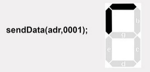
aaaaaa i remember something !!
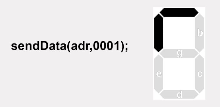
I believe I understand why is showing me this symbol !!!
I made some very simple tests and I believe that the digit is composed from 2 addreses,
First 4bits of address = half of the digit segments and the next 4bits of address is the other half of the digit segments.

I used this code:
  void loop()
  {
    sendData(adr[0],0b0001); delay(200);
    Clear();delay(100);
  }
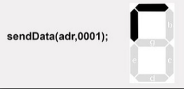
where I changed manually the address number in adr[0] as 0, or 1 or 2.
when Im changing it to 2, it is switching to the second digit.
So to be clear,
adr0 and adr1 creates digit1 from the 3digits of the LCD
adr2 and adr3 creates digit2 from the 3digits of the LCD
and finally,
adr4 and adr5 creates digit3 from the 3digits of the LCD
Next, I made this tested and working code:
    uint8_t seg[8] =
    {
      0b00000000,0b00000001,0b00000010,0b00000100,
      0b00001000,0b00010000,0b00100000,0b01000000
    };

  void setup()
  {
   config();
   Clear();
  }
   /*this Test Code will lit up each segment from the first digit of the 3digit LCD.
    because the first digit is split in two 4bit addresses adr0 and adr1.
    3segments in adr0 and 4segments in adr1
    in total 7segments = 1 digit
    */
  void loop()
  {
      sendData(adr[0],seg[0]); delay(200);
      sendData(adr[0],seg[1]); delay(200);
      sendData(adr[0],seg[2]); delay(200);
      sendData(adr[0],seg[3]); delay(200);
      sendData(adr[0],seg[4]); delay(200);
      sendData(adr[0],seg[5]); delay(200);
      sendData(adr[0],seg[6]); delay(200);
      sendData(adr[0],seg[7]); delay(200);
      Clear();delay(500);

      sendData(adr[1],seg[0]); delay(200);
      sendData(adr[1],seg[1]); delay(200);
      sendData(adr[1],seg[2]); delay(200);
      sendData(adr[1],seg[3]); delay(200);
      sendData(adr[1],seg[4]); delay(200);
      sendData(adr[1],seg[5]); delay(200);
      sendData(adr[1],seg[6]); delay(200);
      sendData(adr[1],seg[7]); delay(200);
      Clear();delay(500);
  }